Ball Clock II ~ Counter Reset

Photo 062
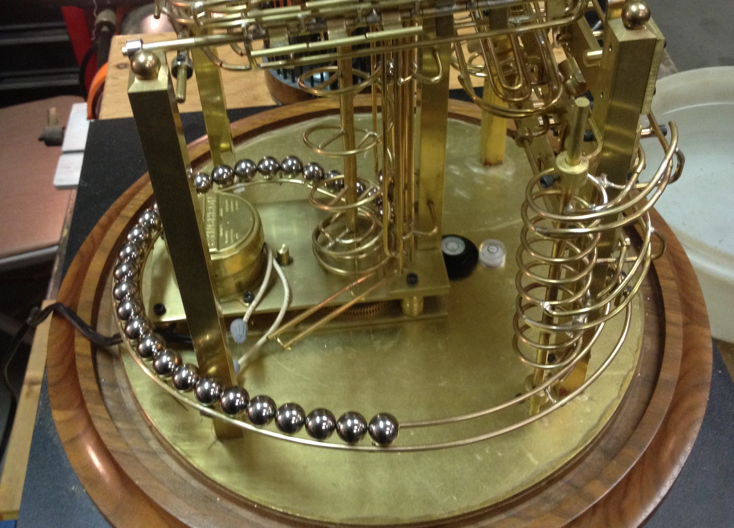
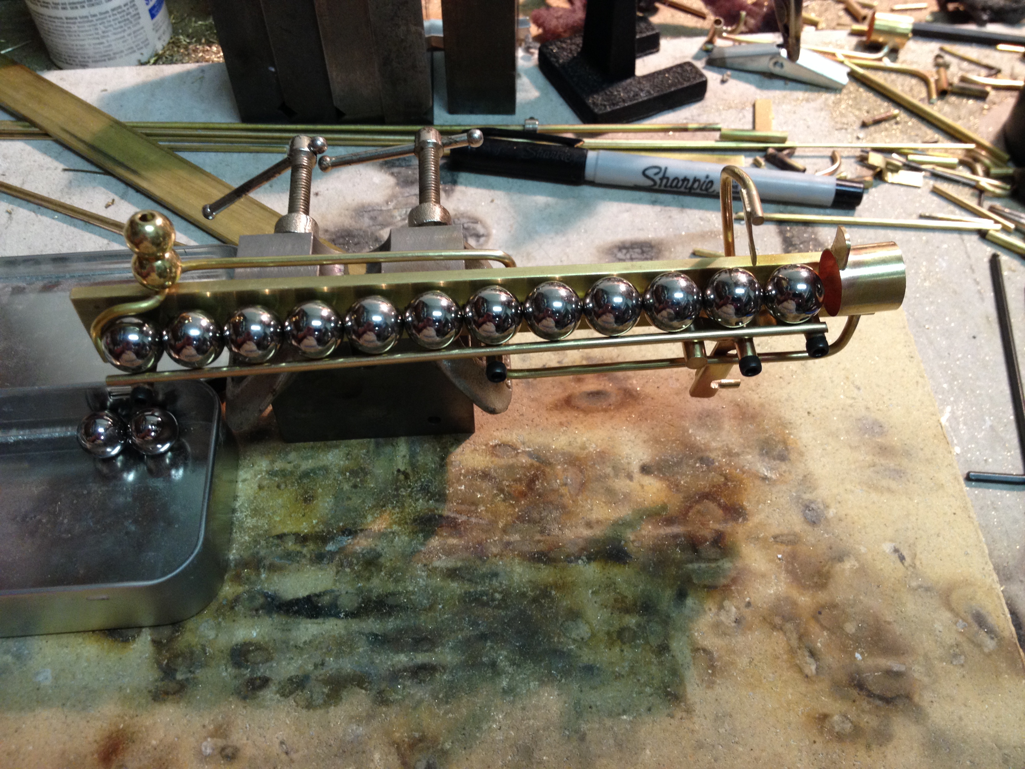
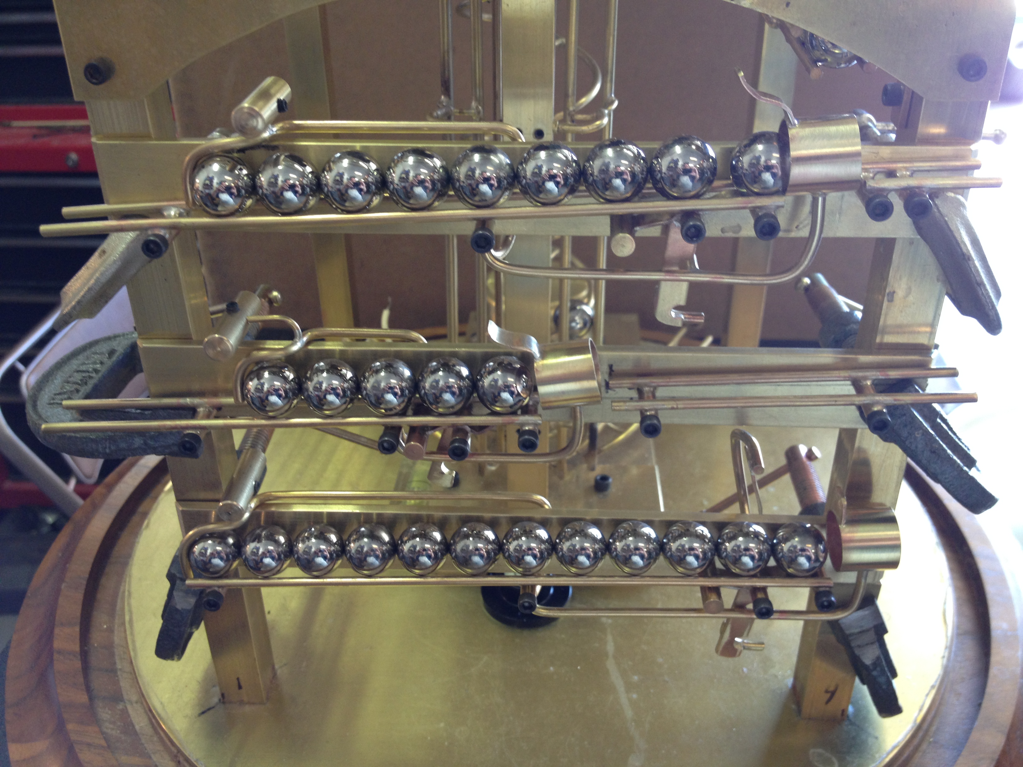
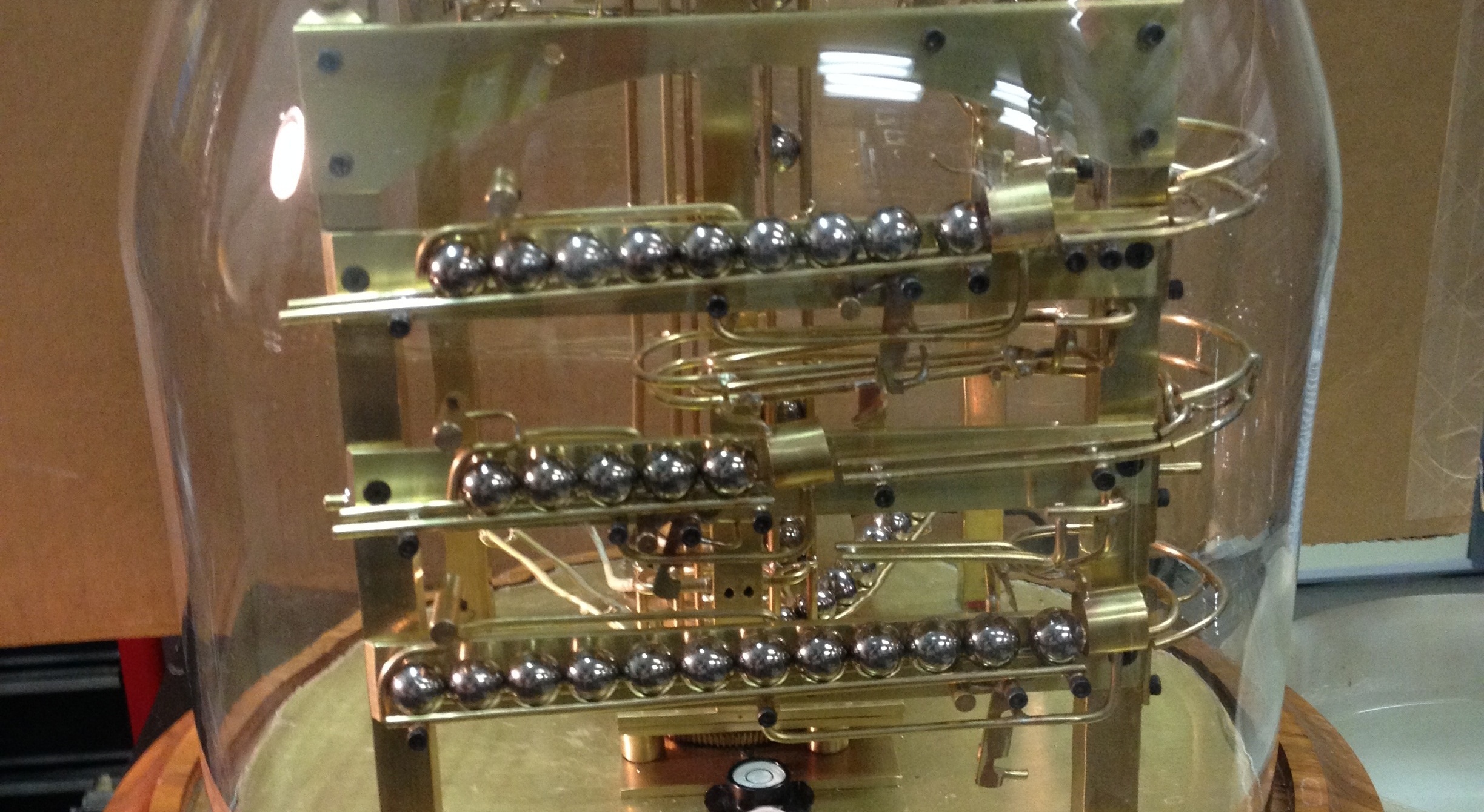
Now that the ball clock can run and keep time, the next step is to work on the counter and get it reset at the appropriate times.  The concept of the counter is to have a ball flip another small section of track with every pass on the way to the minute rack.  With every flip the upper track grows longer until it reaches a section that will count the 15, 30 & 45 minute passes.  This is composed of three flips for that purpose.  When all three of these are flipped, the ball will end up in the hour section.  Don’t know what that will look like yet.

Photo 061
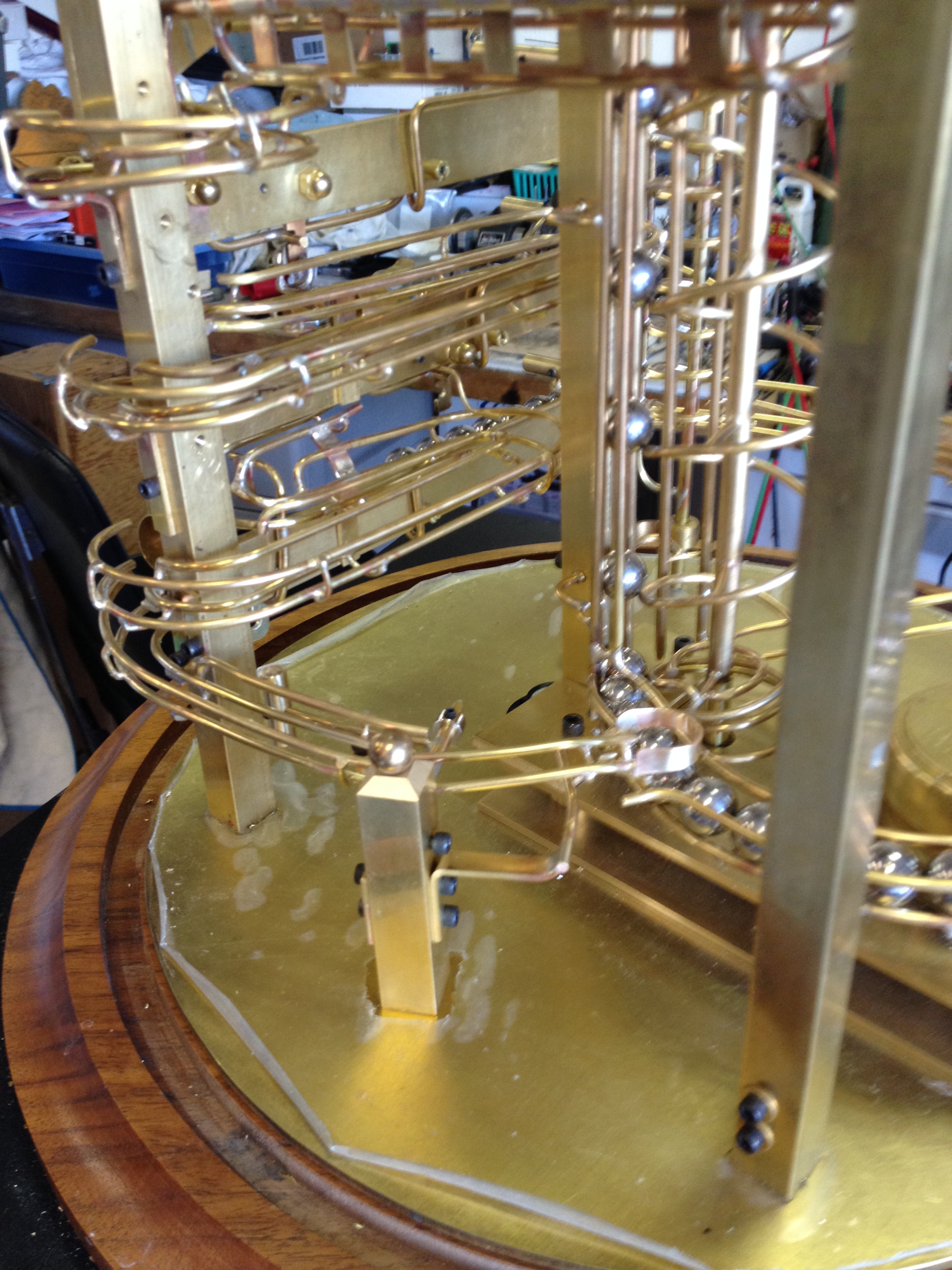
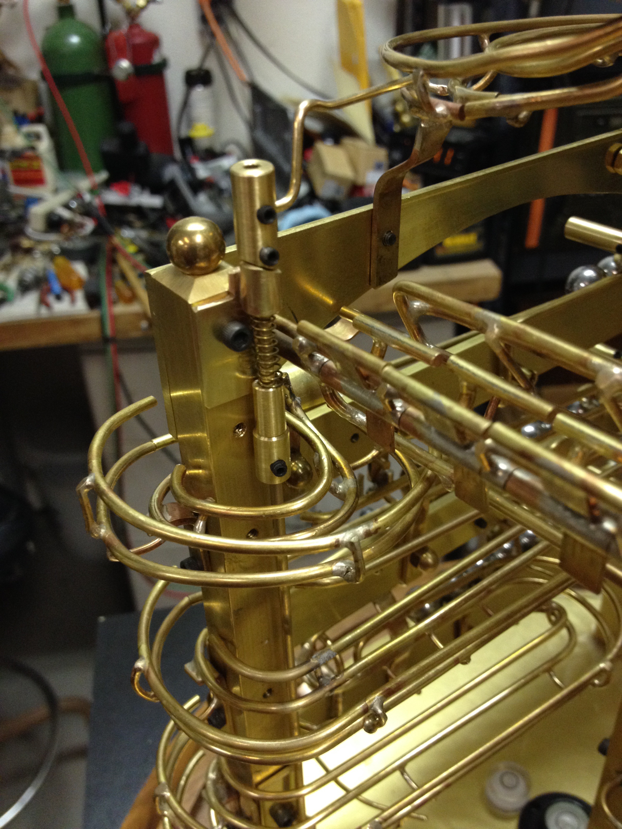
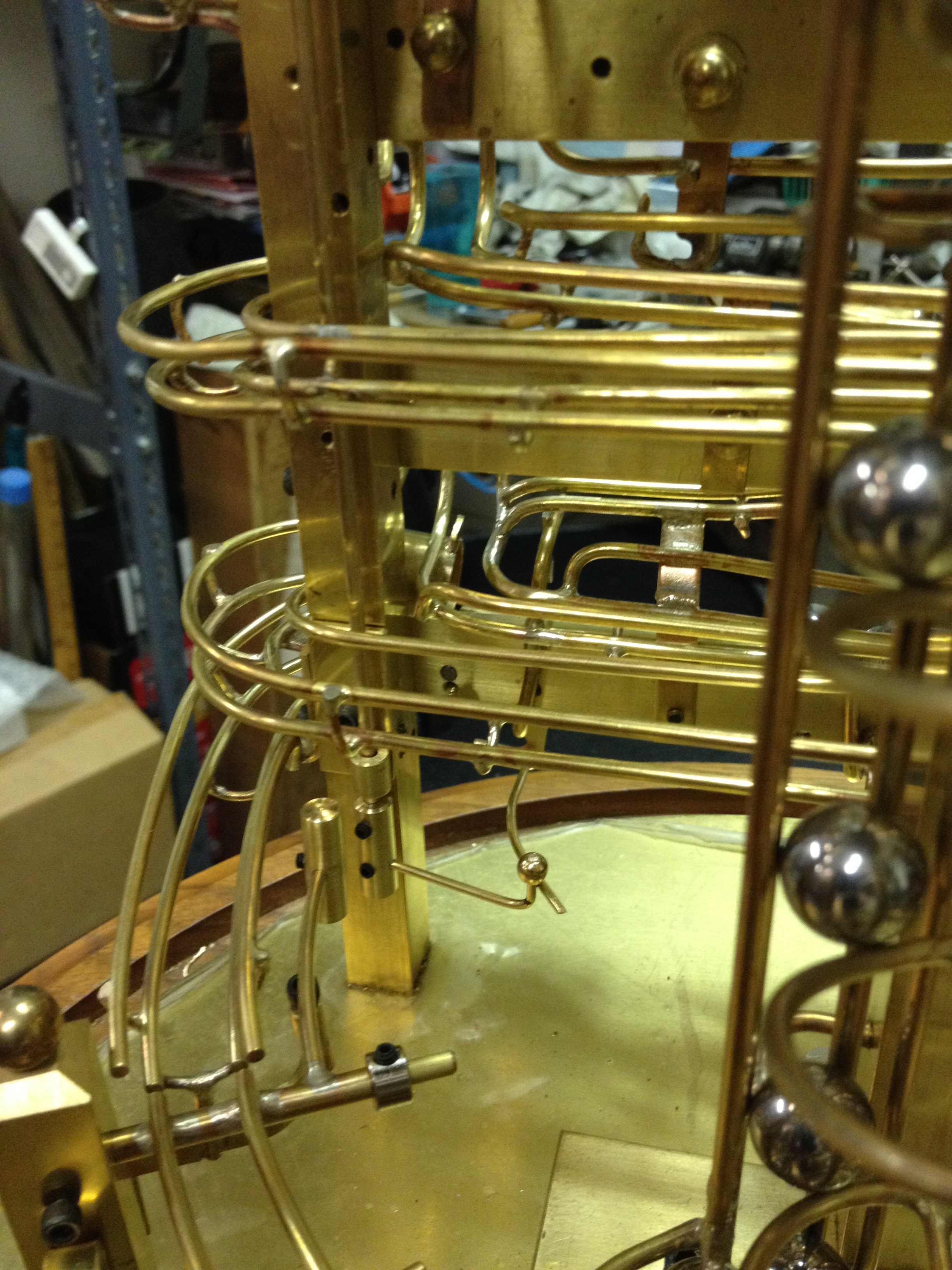
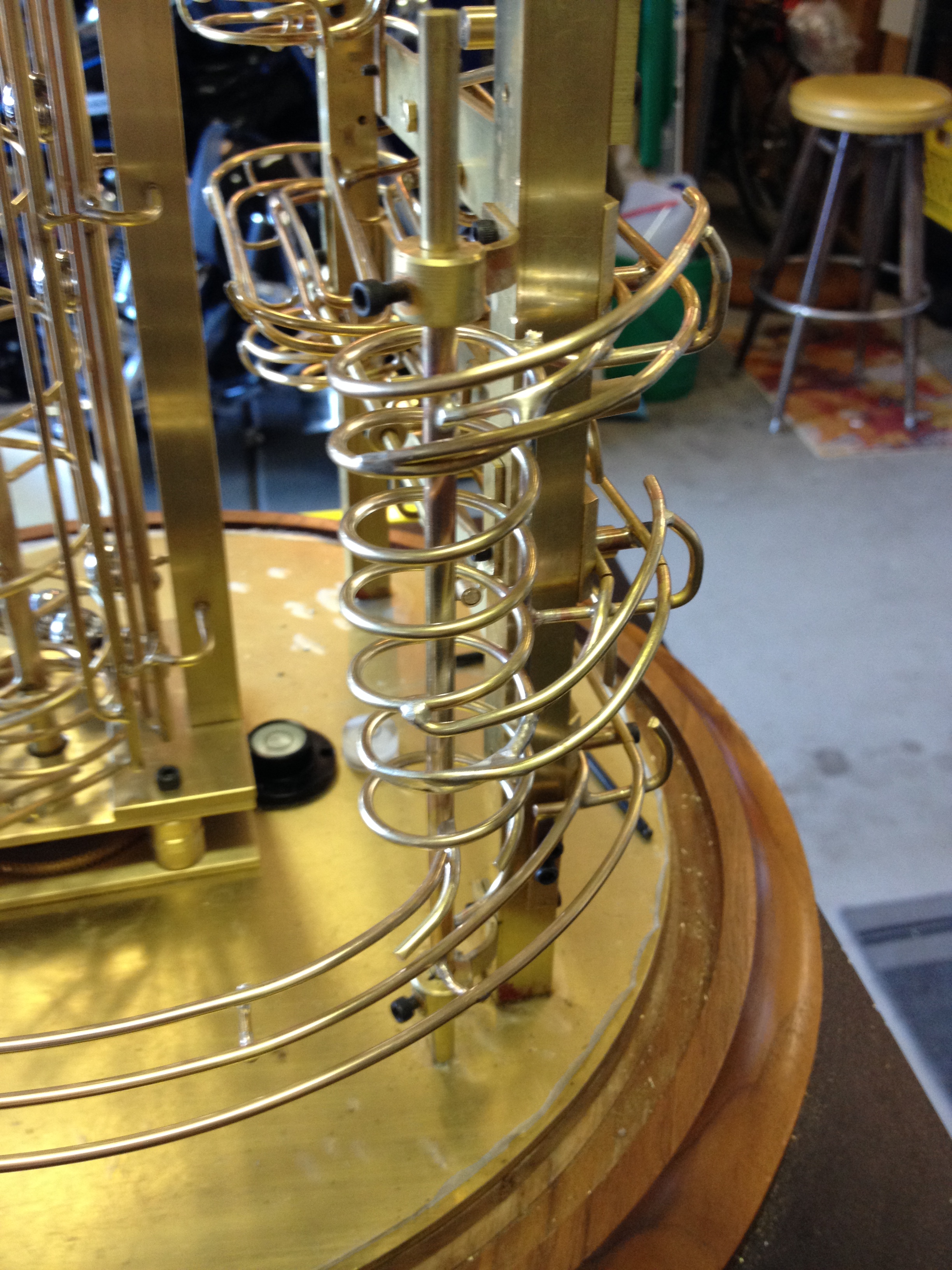
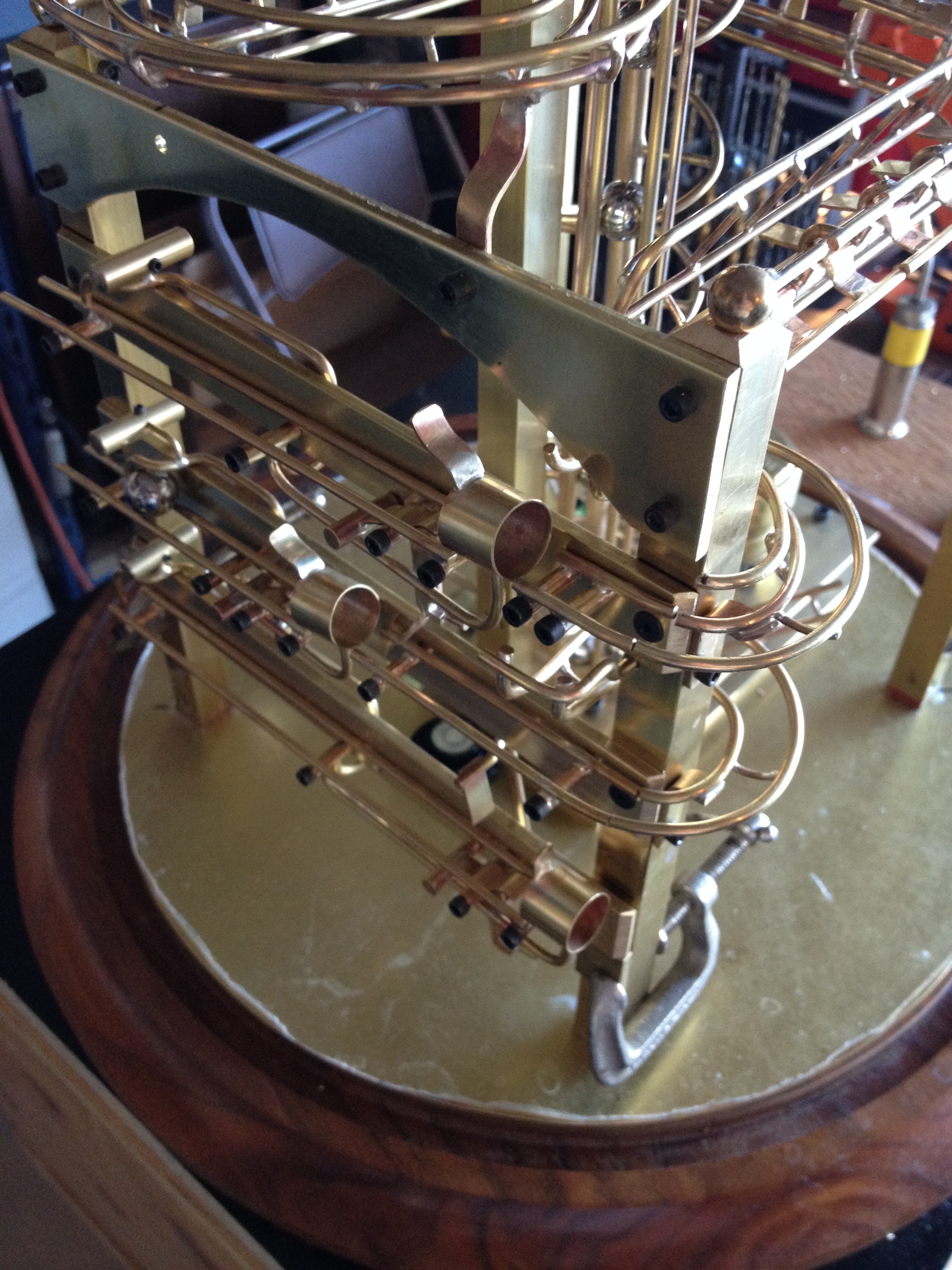
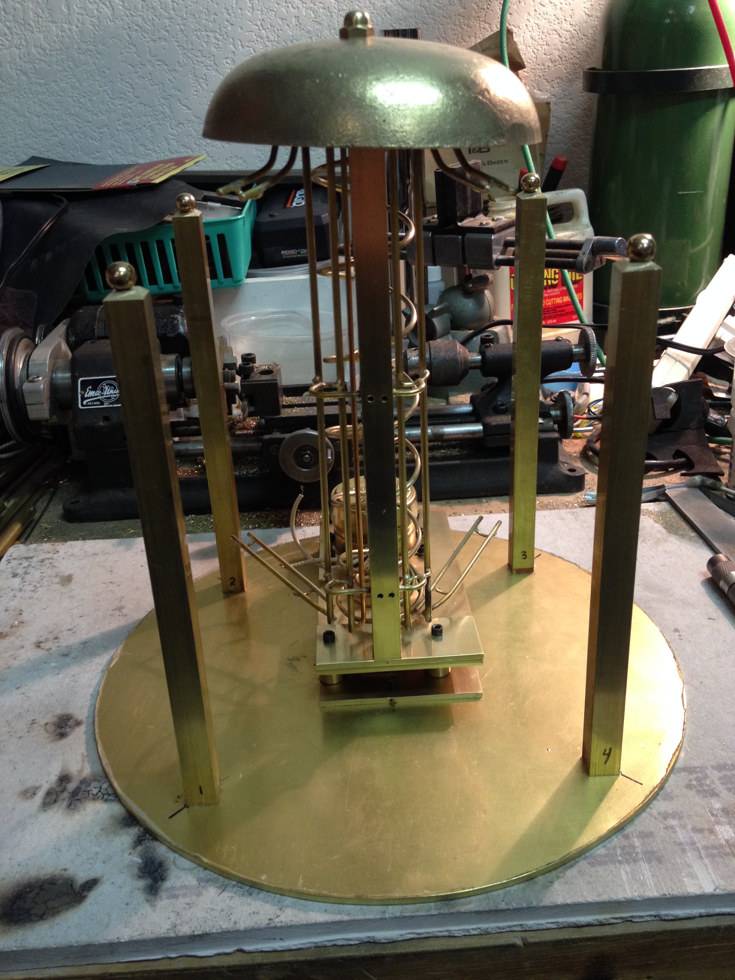
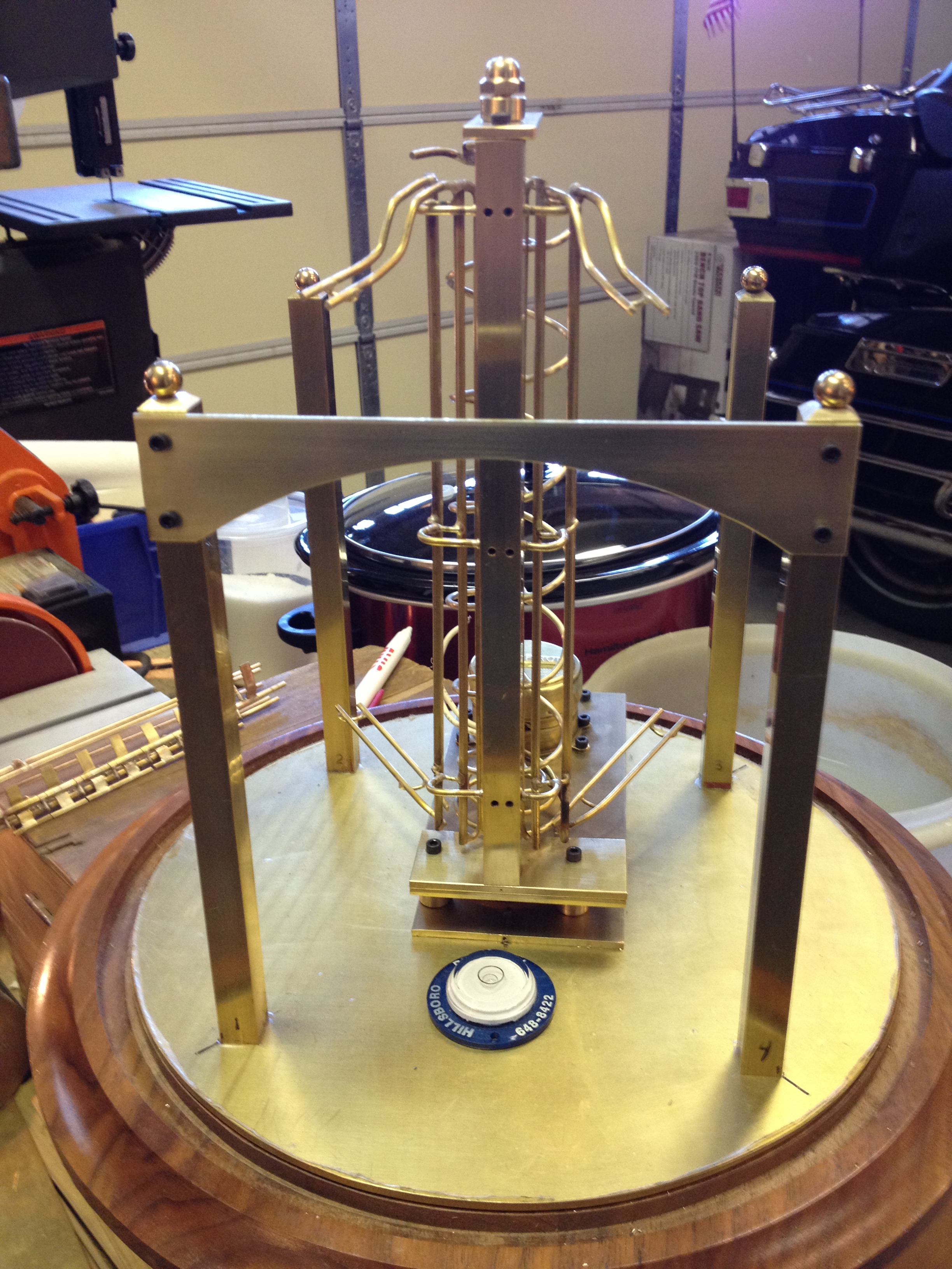
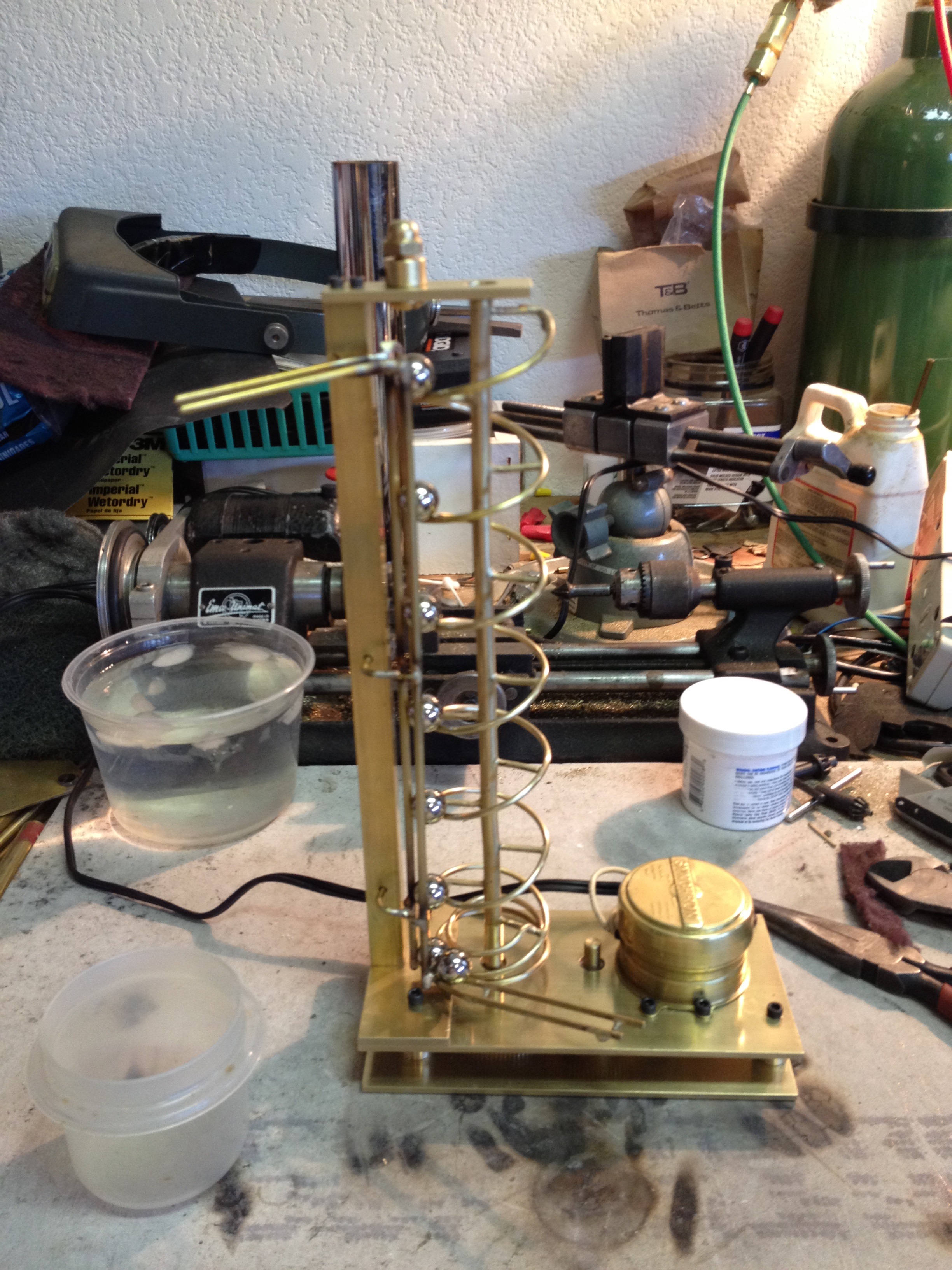
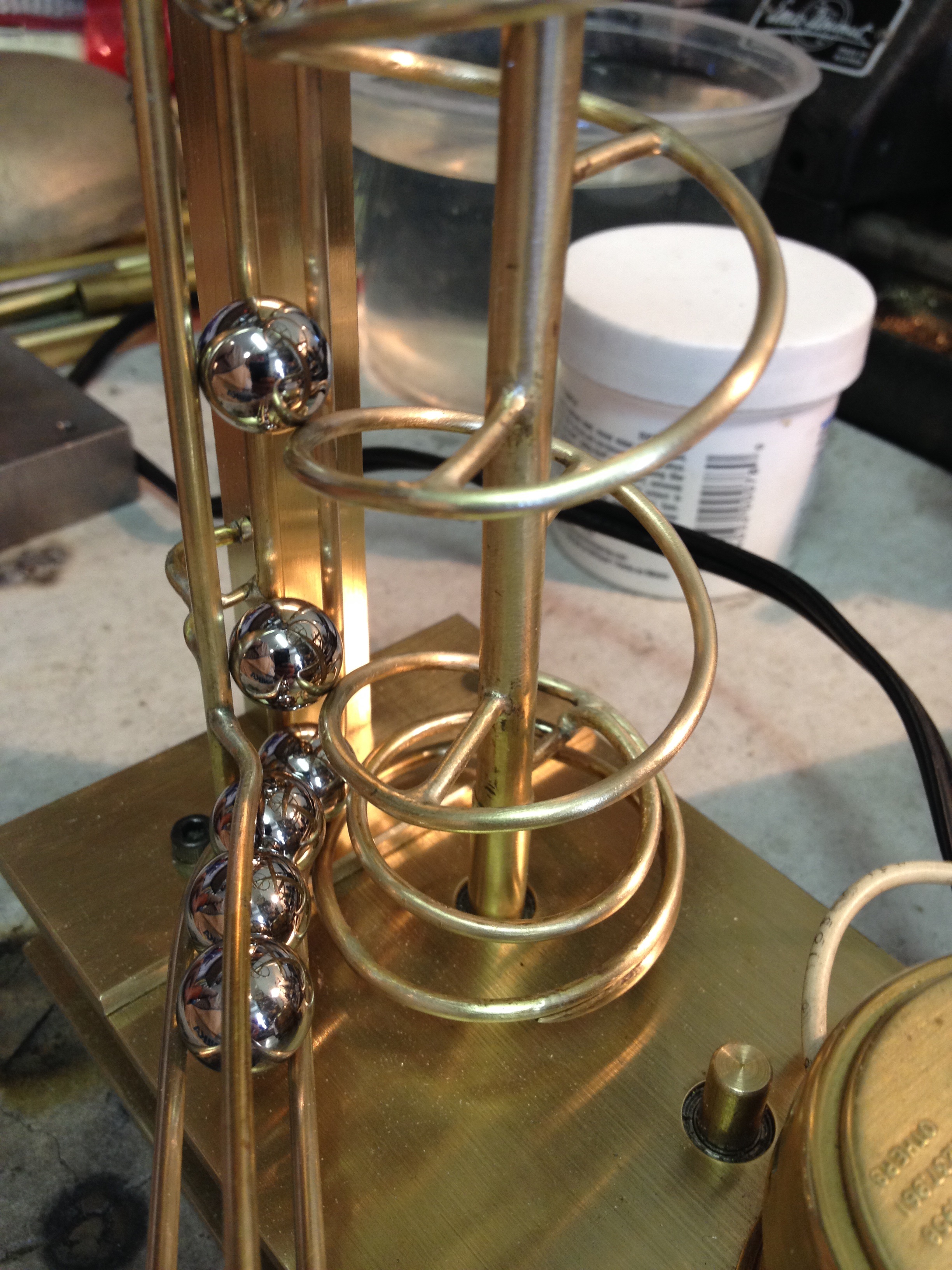
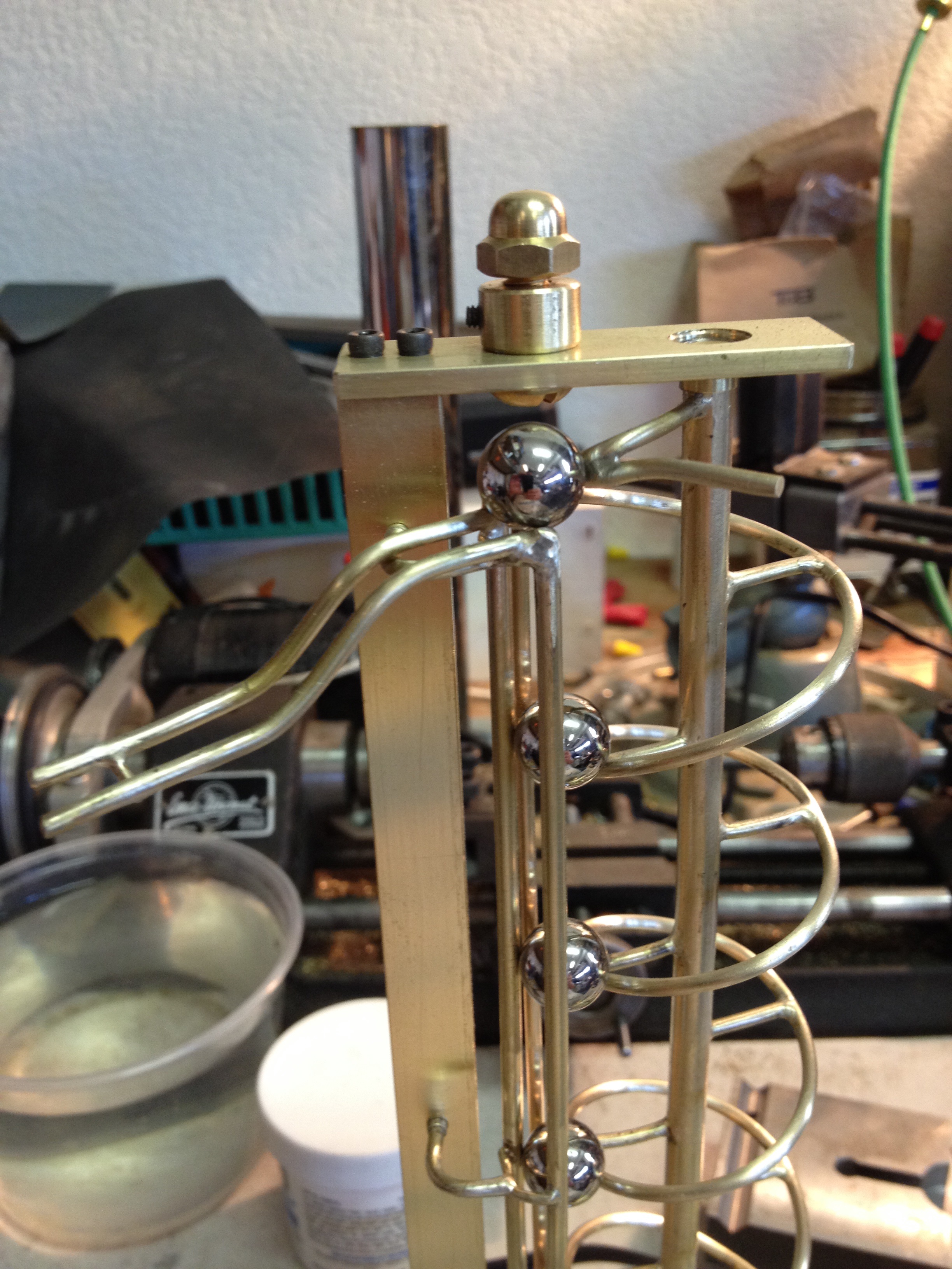
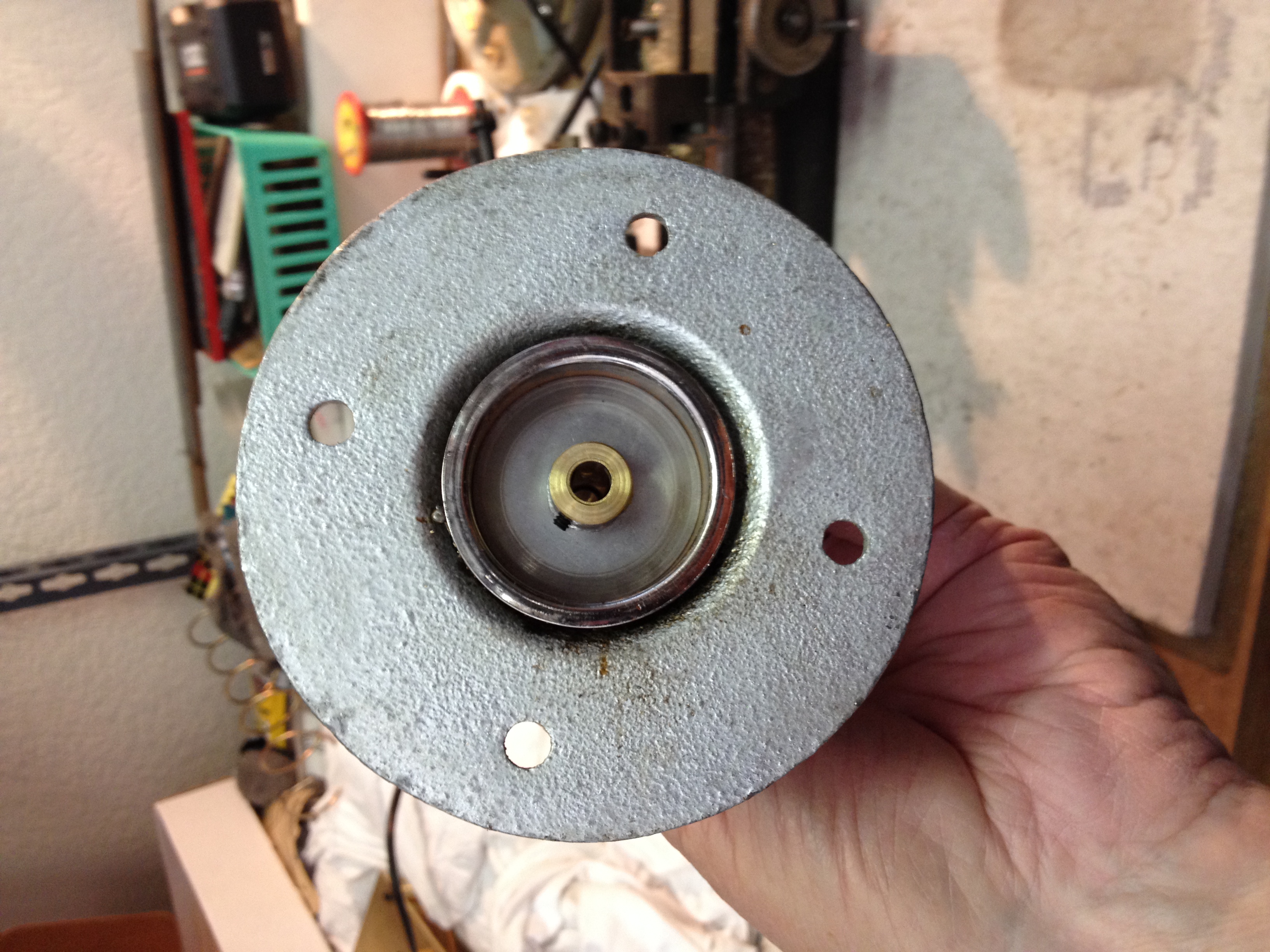
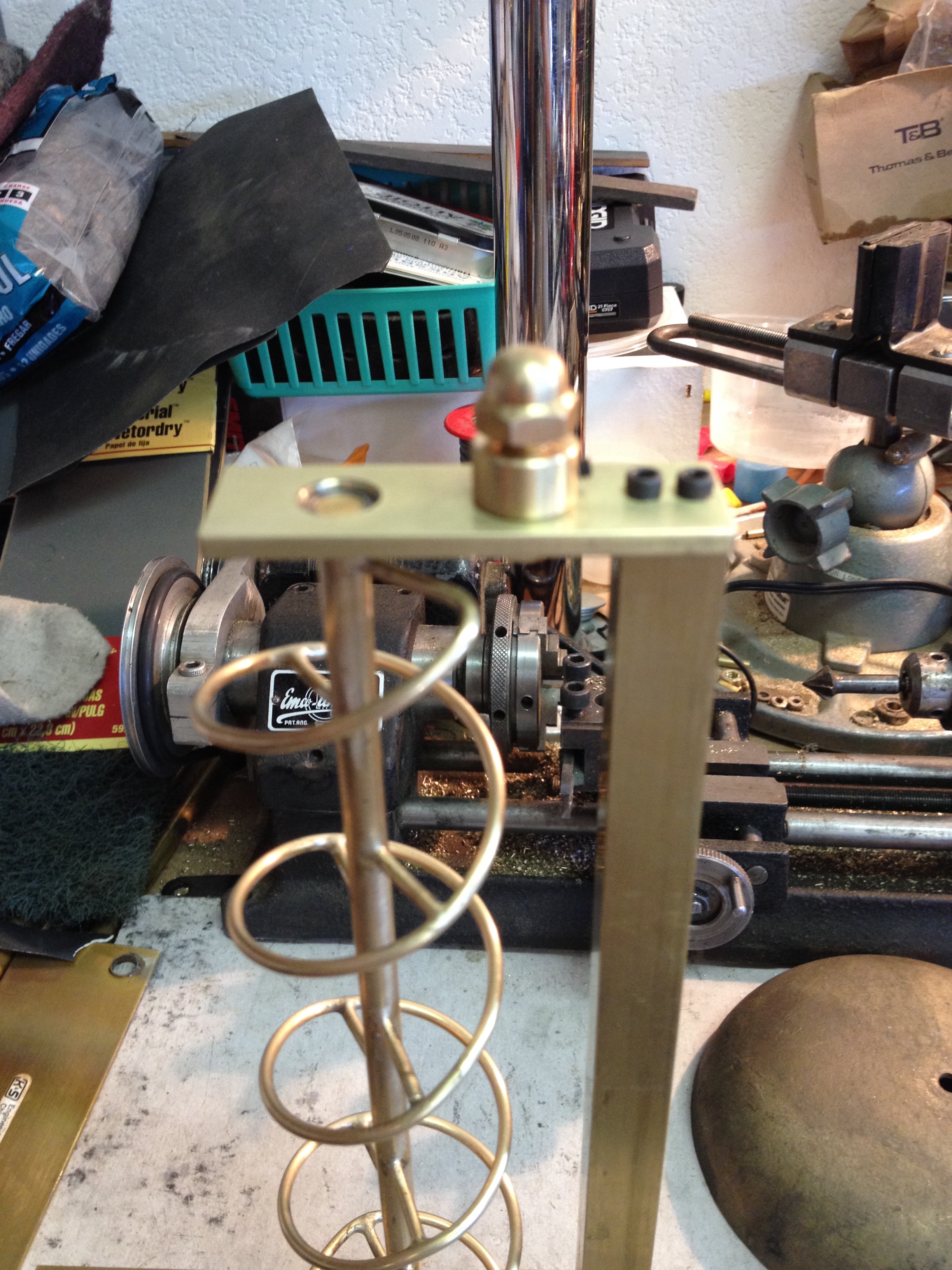
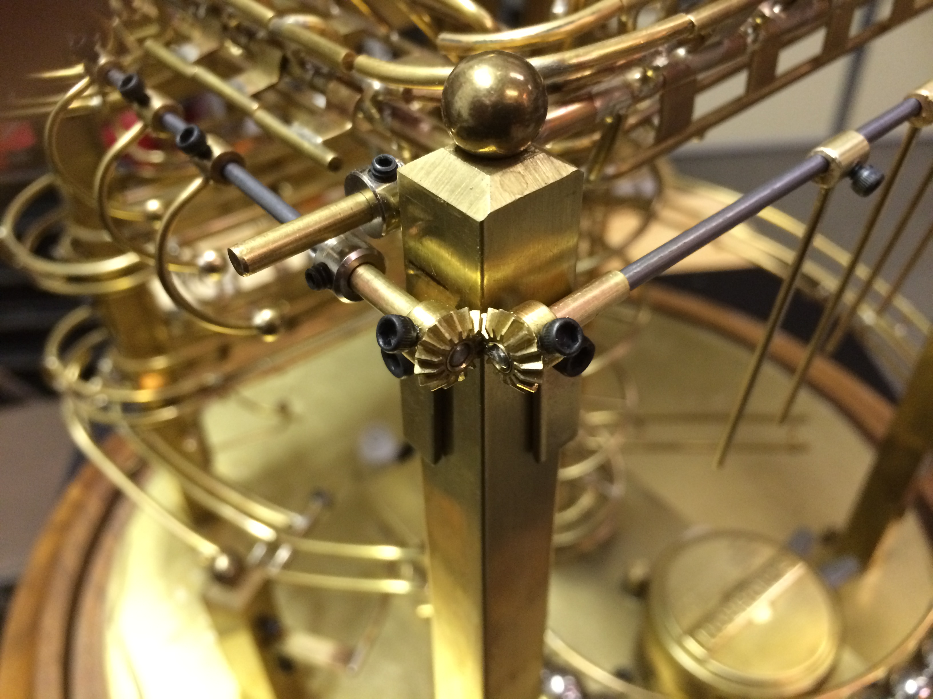
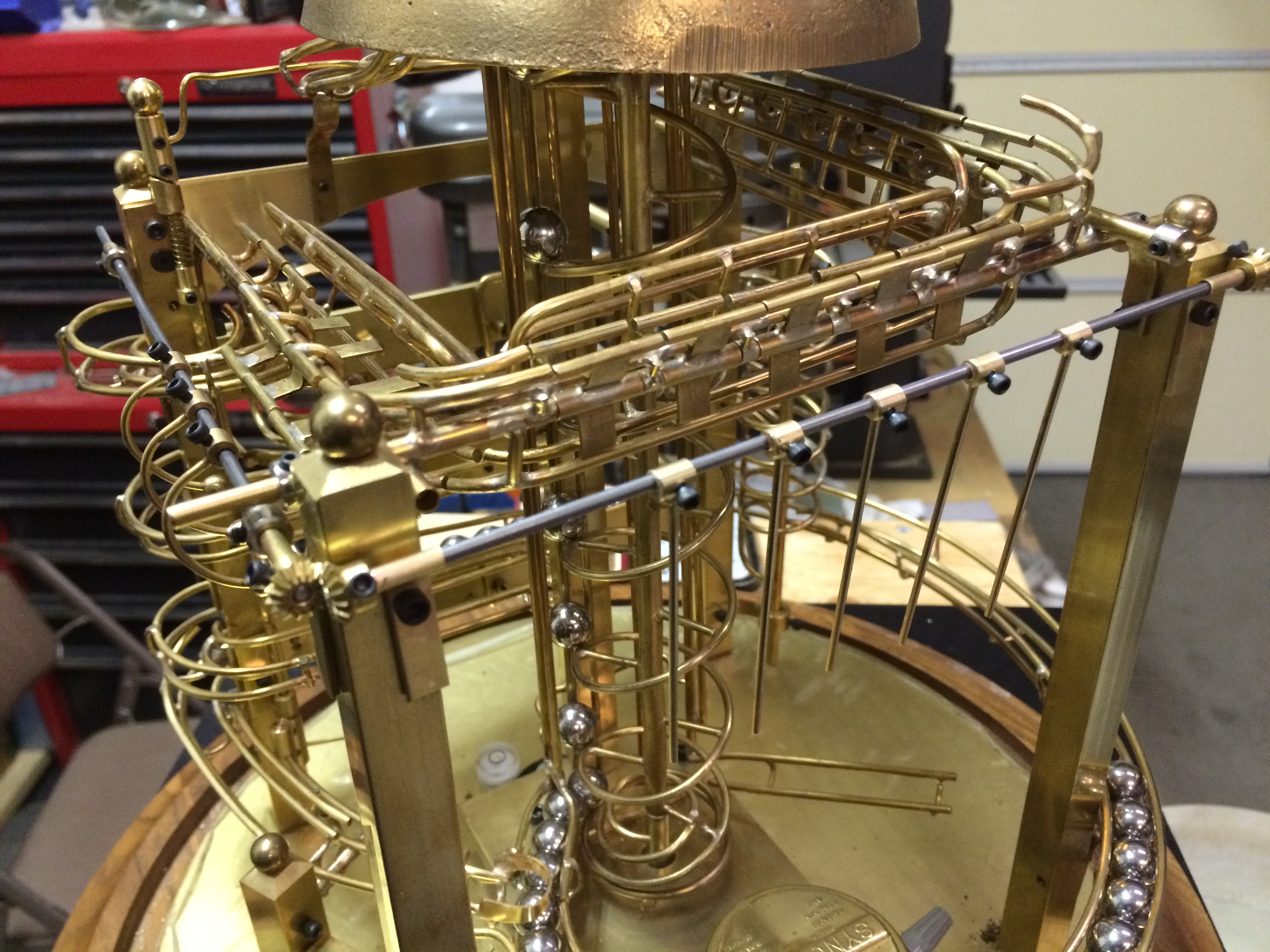
So, the first thing is to reset the flips.  They are on three sides of the clock and must work in unison.  Arms are created to rotate and push up from the bottom to restore the flips.  Miter gears are used on two corners to rotate the shafts that will reset the flips.  Because the track has a gentle slope with variances in distance from the frame, it became necessary (after a couple of attempts) to have two shafts involved.  one that aligned with the track and one to provide the power for the reset.

Photo 065
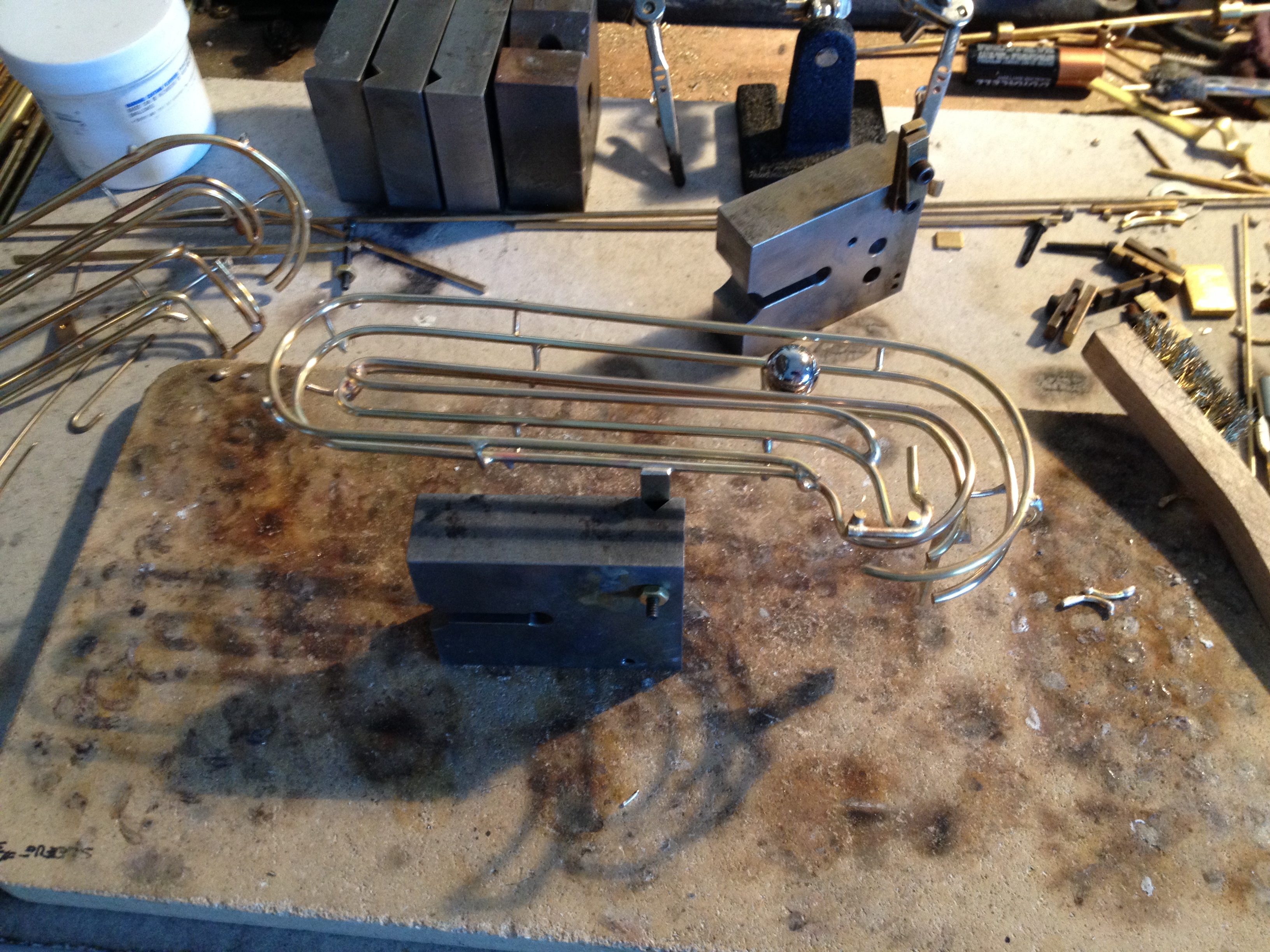
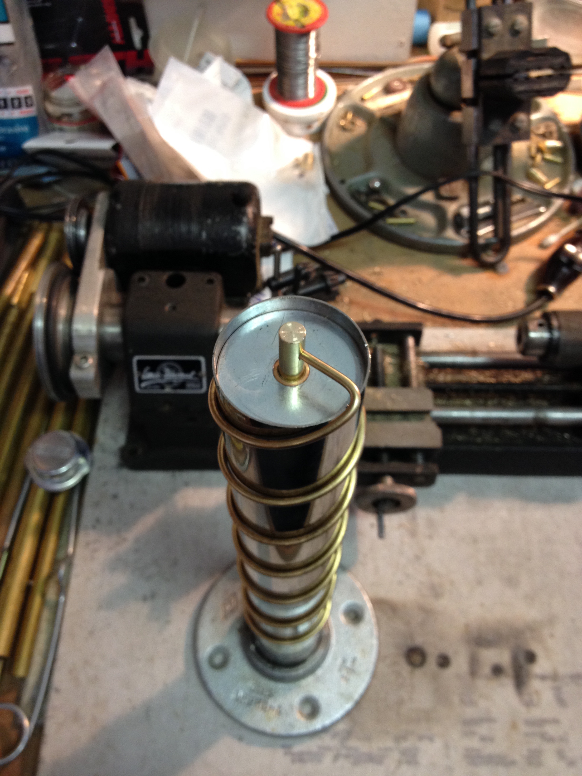
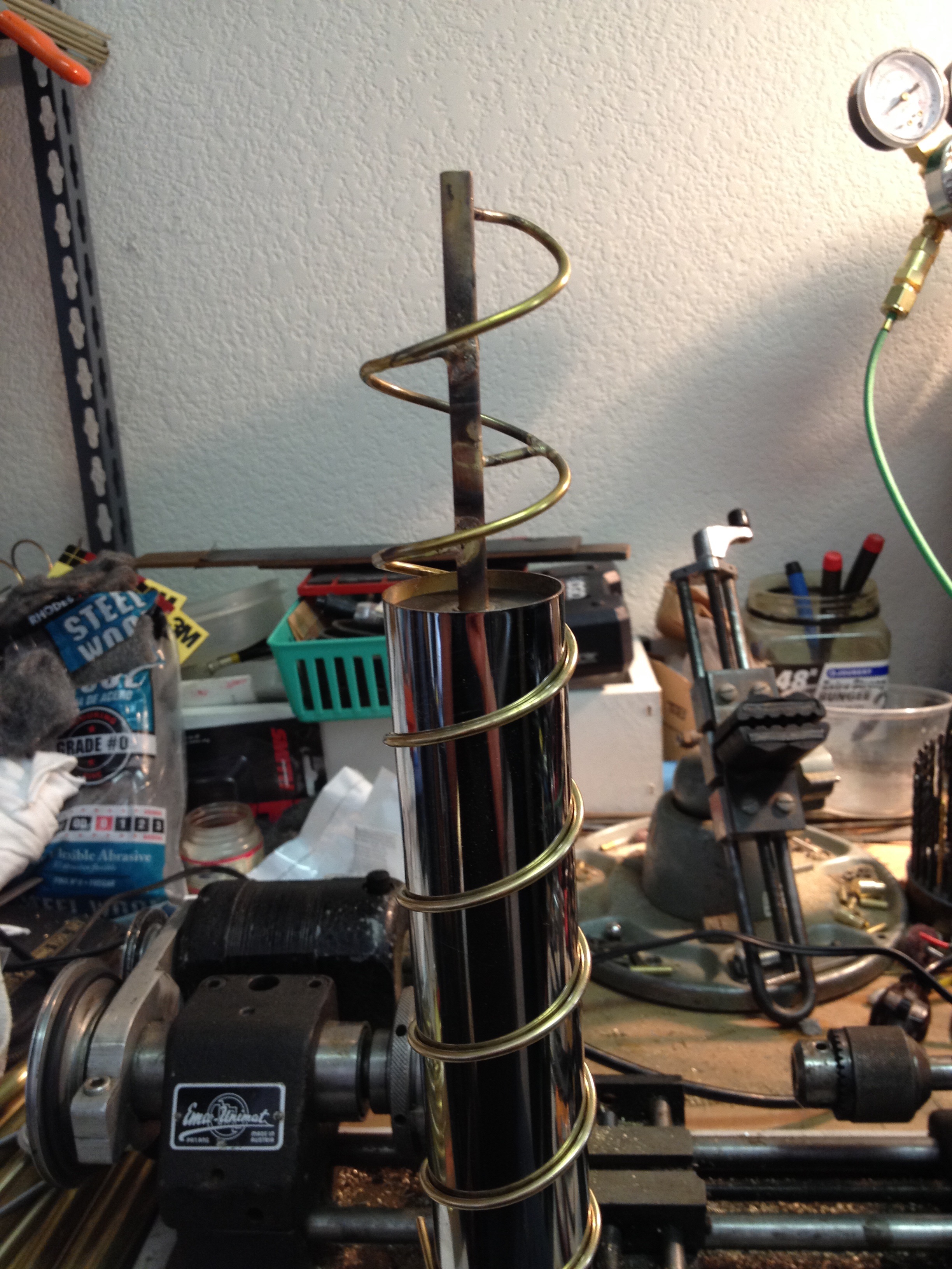
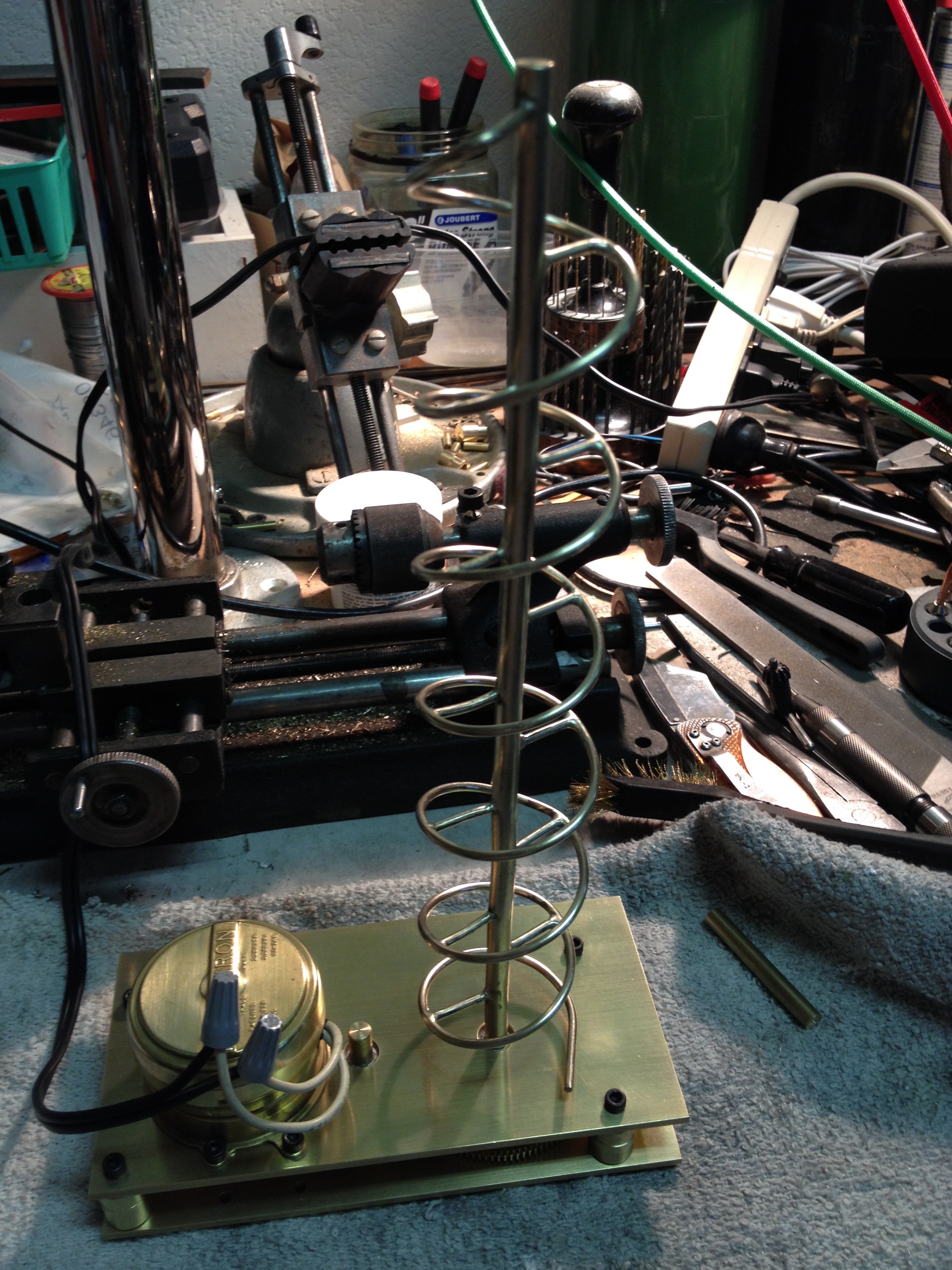
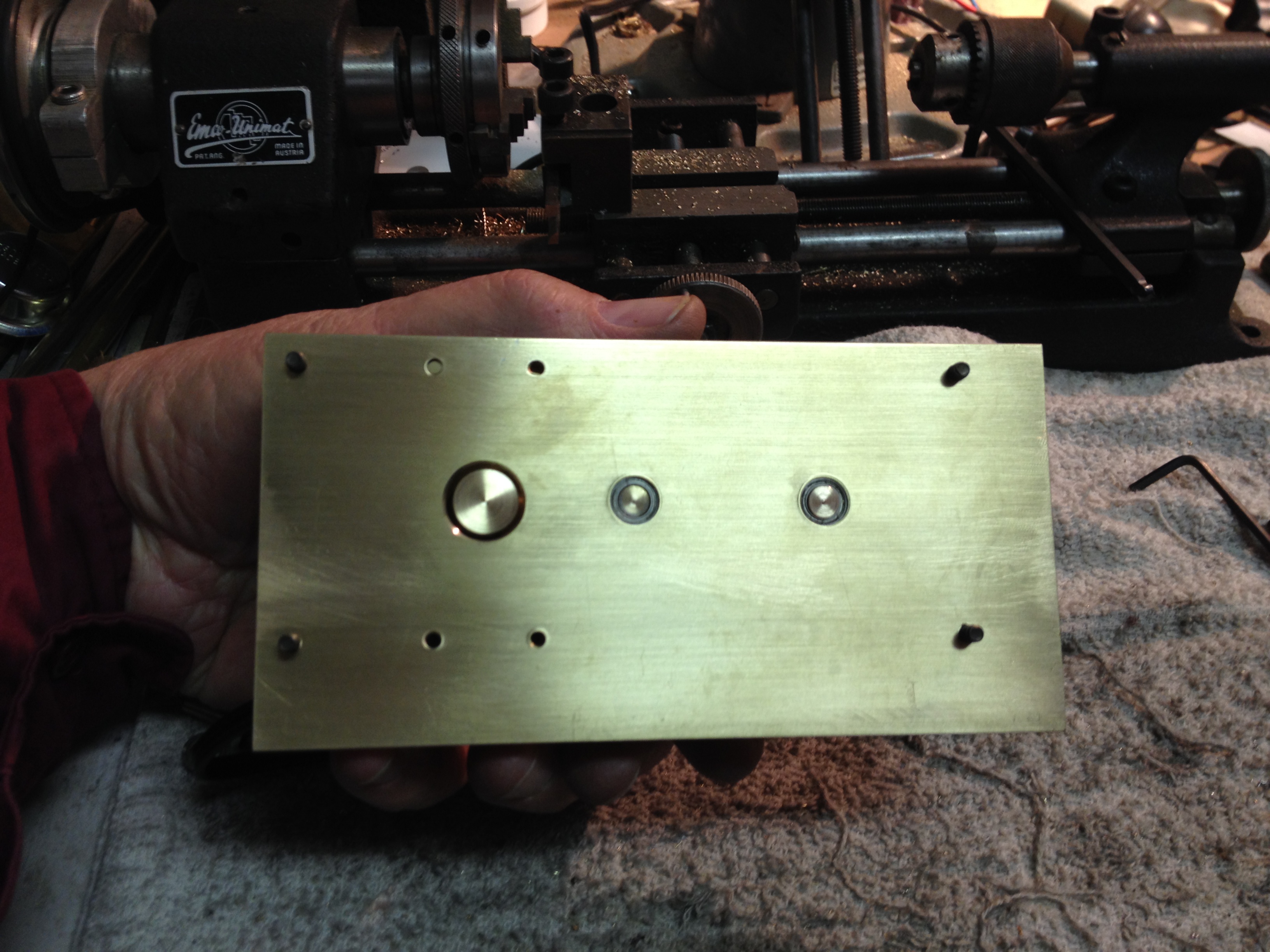
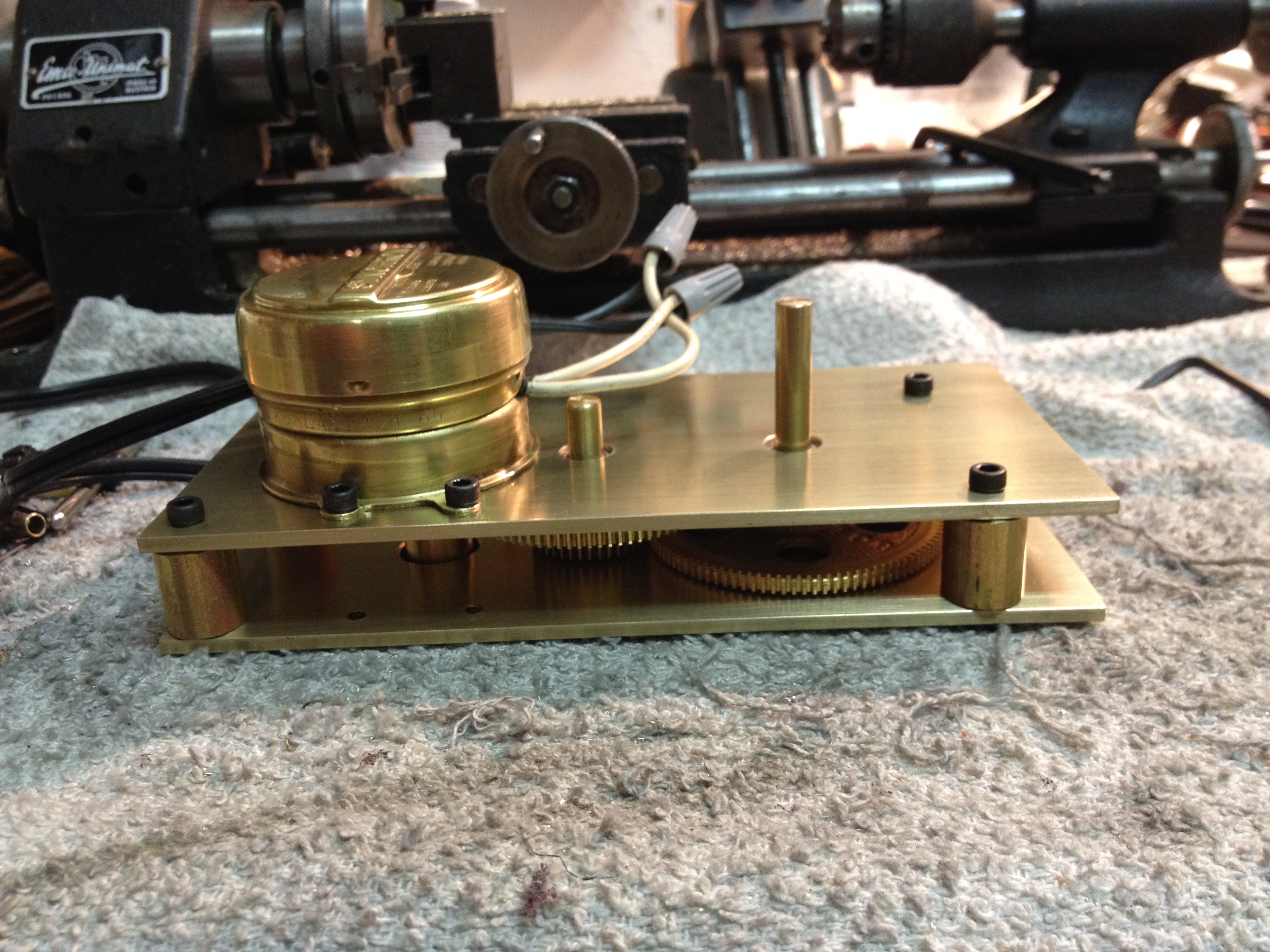
I used Boston Bevel Gears again because they are a great product and just the right size, albeit somewhat expensive at $10 each.  The trick here was to create a drive train that would easily reset all the flips with a minimum of effort.  Each reset arm had to be adjustable because of slight variances in the slope and flips.  This is not a precision timepiece and no milling machine is being used so there are variances.

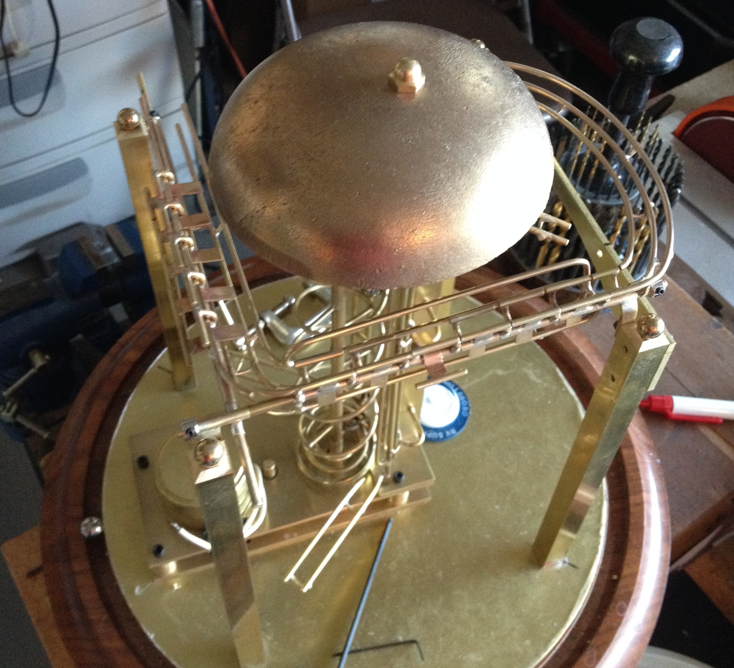
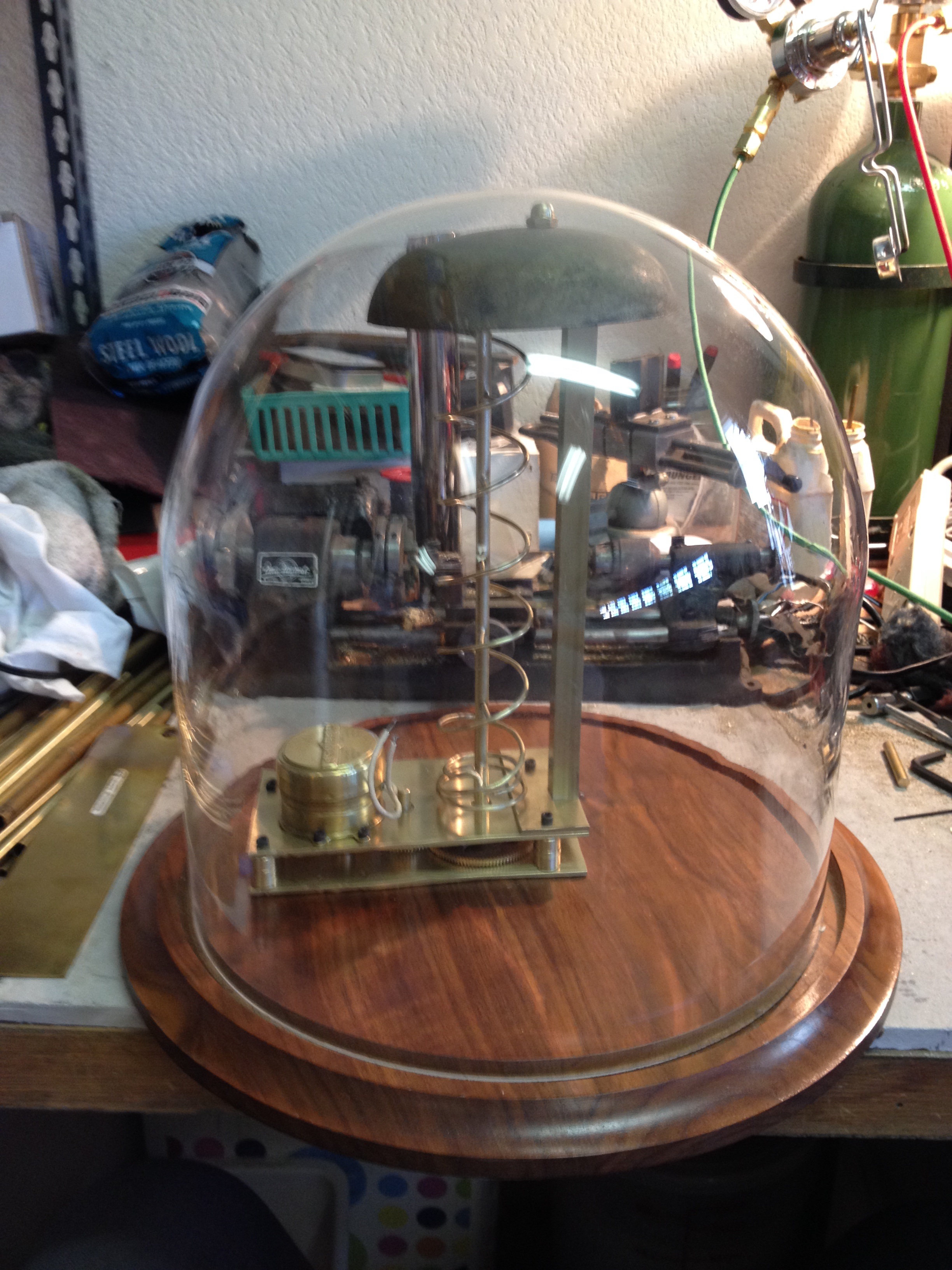
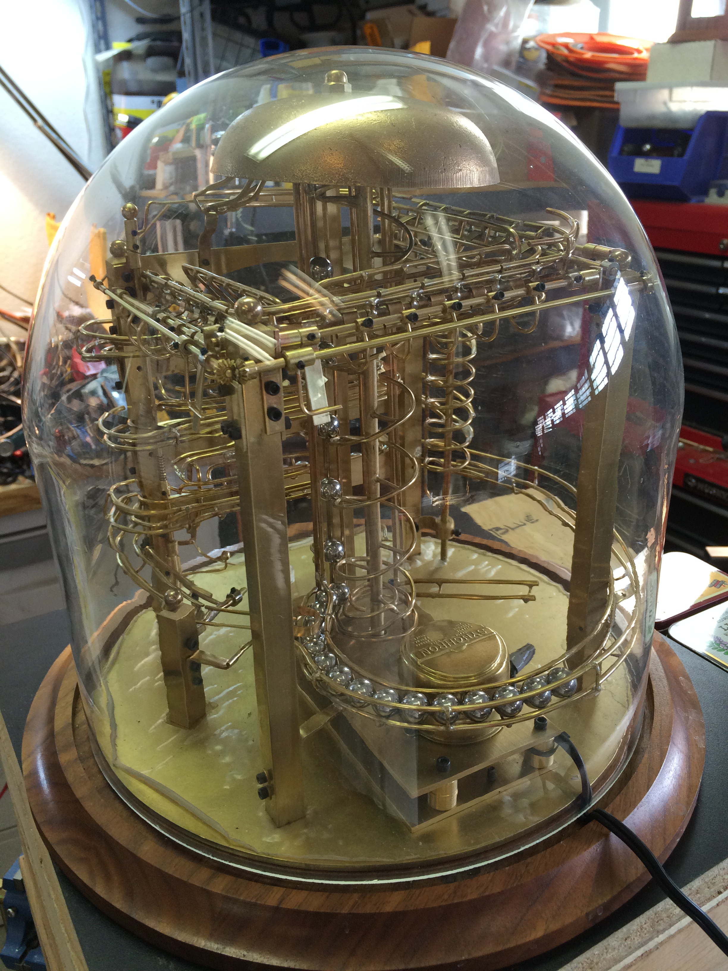
With the dome on, I check the clearance for the gears and discover that, “it is better to be lucky, than good lookin'”, sometimes.  There is barely enough room as the dome curves into the top round.  Having the power cord attached lifted the dome slightly and I didn’t realize just how close it was until I disconnected it.

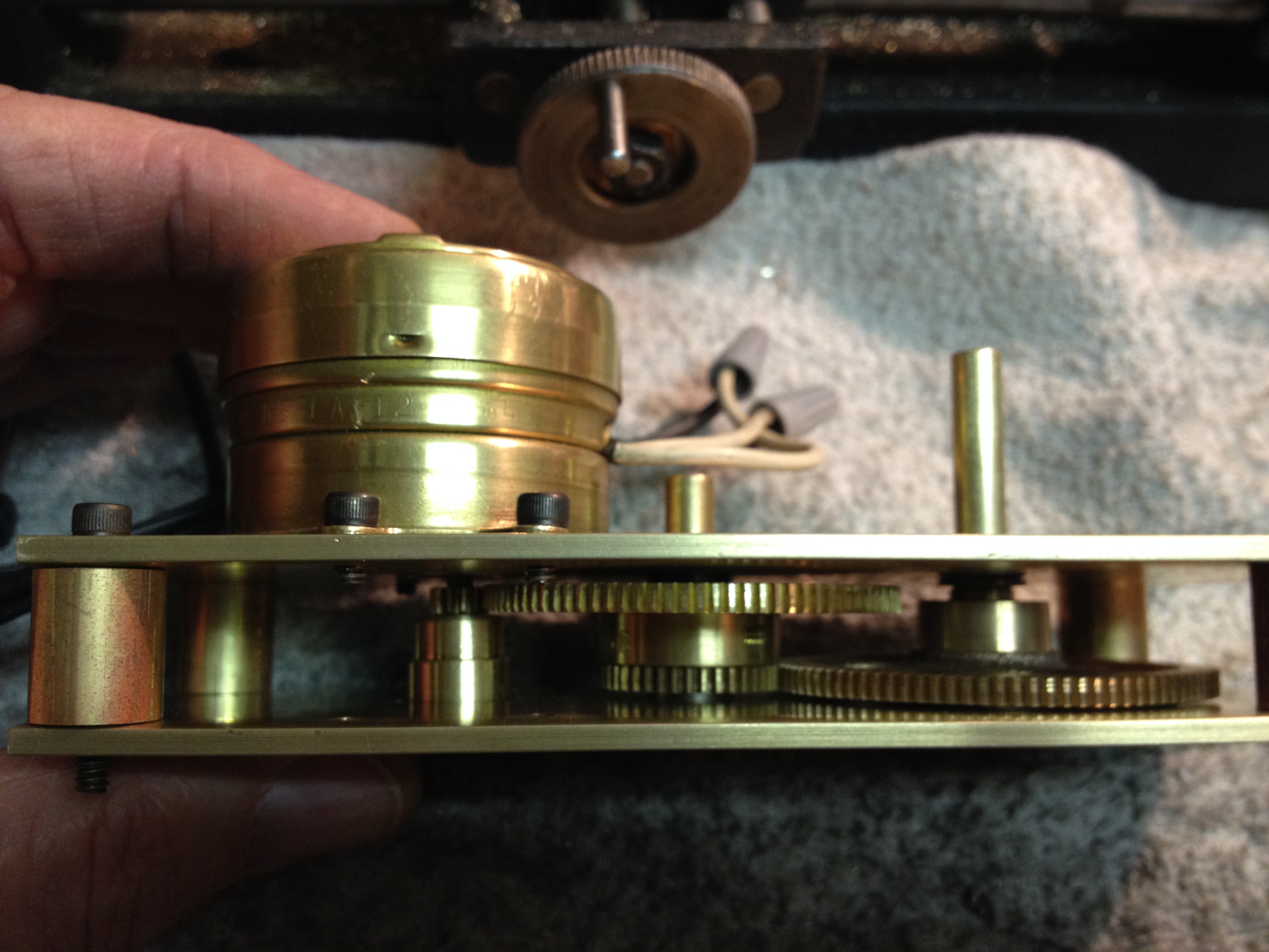
Now that I have the reset shaft assembled and working by hand, the next step is to figure out how to trip the reset at the right time.  I will need power to do it and it is obvious that I do not have enough balls to do the job.  Ok, so I could have said that differently.

It is obvious I will need to get power from the drive train below.

The movie shows me manually resetting the flips.

Posted in Ball Clock | Tagged | Comments Off on Ball Clock II ~ Counter Reset

Ball Clock II ~ One O’clock Ball

photo 058Having completed an exit path for the balls on the time racks, the extra ball at one o’clock had to have a way to blend back into the lift.  There was not enough elevation left at this point for it to wrap around on a track and join the others.

The simplest solution appeared to be dropping it onto the others just before the lift.  The idea was to let the weight of the ball stop the other balls coming in from the right while allowing to lift to create a gap in the line for the one o’clock ball to fit in.  A short post was added to provide support for the short track and pivot point allowing the track to drop against the other balls.  The ball will sit there until a gap opens up.  Once it drops in, the track lifts back up just enough to let the rest of the balls back in line.

It was a lot of theory here, but happy to say it worked.  Better yet it worked every time.

IMG_3466IMG_3467The hour rack is still tipped at this point and must be reset before it can accumulate more balls.  Plus the one ball that was captured when it tripped needs to go to the left end of the rack to display the proper time.  The simplest solution seemed to be to reset the rack on the next minute ball that came from the lift.

So a lever was put in the path of the balls just as they came down the ramp from the lift.  The ball would push the arm out of the way, rotating a shaft that went down to the latch holding the rack arm tripped.  Once released, the captured ball rolls to the left end of the rack.

With that, I can let the clock run 24 hours for the first time.

It is times like these that make me think I should have stuck to conventional approaches, instead of doing something different.  But then again where would the challenge be?

To much of that goes on in life the way it is and we can find ourselves in the “proverbial rut”.


Posted in Ball Clock | Tagged | Comments Off on Ball Clock II ~ One O’clock Ball

Ball Clock II ~ Ball Exit Path

photo 047 CroppedHaving mounted the ball racks and able to cycle the balls through the various time configurations it is now necessary to provide a path for the balls to return to the lift.  Tight quarters dictated tight solutions.

In any ball sculpture, people seem to respond to a spiral.  It seemed a good place to put one for the minutes and tens of minutes release.

Forming the spiral was about as much fun as making the lift spiral.photo 052  Except that an entry point was needed along the way for the tens balls.

Let’s just say it took more than one attempt to get it working.

A track was also needed to blend the balls back into the lift.

Once the spiral and return track were completed it was time to fire up the clock for the first time.

When a trip ball arrives at the rack, the weight of the ball tilts the release and the balls on the rack exit stage left.  It is necessary to keep the release lever up until all balls have exited.  This is done by the trip ball taking another track down to the next level and along the way releasing the release lever to return to the normal position. photo 060 There is timing involve here.  The trip ball cannot restore the release lever too soon.  This was happening with the minutes rack about every tenth time.  Just enough to let me know it was going to be an issue.  The solution was to extend the time it took for the trip ball to reach the release lever.  I had to remake the section going from the minutes to the tens of minutes rack over to increase that time by about 1.5 seconds.  It worked!

Sometimes it is the little things…

Of course there still wasn’t a way to deal with the 1:00 o’clock ball.


Posted in Ball Clock | Tagged | 2 Comments

Ball Clock II ~ Ball Racks

Having completed a path for the balls to arrive at the minute rack the trick was to come up with a way of doing it different than others I have seen.photo 033

I started with the hour rack because it had the most balls and if I could work that one out, it would be time to start all over.  As I said earlier, one of the challenges of this project was to fit everything into the dome.  As it turned out, I had just enough room to rack 12 balls.

The hour rack is unique because at 12:59 and one minute, there has to be one ball left in the rack to represent 1:00.  Conventional ball clocks will capture one ball in the rack so it cannot be released with the others.  photo 035This proved to be a challenge because of the way I chose to rack and release the balls.  This first photo shows the hour rack on the bench.  To the right between and above the first and second ball is a blade which when the balls are released, the blade will keep one ball from exiting the rack.

This all happens when the hour ball for 1 o’clock tips the lever to release the balls.

The other racks a pretty straight forward.  The ball that trips the rack will continue down to the next level.photo 040

With the 1 o’clock trip ball it will be necessary for it to return to the lift.

I mounted the first rack on the bottom and worked up from there just to make sure I had enough vertical room to return the 1 o’clock ball.

The trip of the rack occurs when there is a ball in the full position. That pushes back a latch that had been keeping the release from tipping when a ball passed through the tube on the right end. I.e. 9 for minutes, 5 for tens of minutes and 12 for the hour.

The balls will have to return to the lift once they have exited the rack.

Again the limited vertical resource came into play as I had to make sure there was just enough drop for the balls to exit the rack without over doing it.photo 041 Cropped  One ball is not an issue but when you have 12 stacked against each other, there is friction against them moving to consider after they have been stationary for 12 hours.

Racks are mounted, but the balls have nowhere to go.

This last photo shows what 12:59 would look like.

This video shows the balls cycling through the racks.  They still have nowhere to exit, so had to improvise.  The 1 o’clock ball is captured and I have to manually release it to go to the left end of the rack.  That will come next.


Posted in Ball Clock | Tagged | Comments Off on Ball Clock II ~ Ball Racks

Ball Clock II ~ Counter

Flipper 30Having completed the frame uprights the next task is to figure out how to count the balls so that I can strike the 1/4, 1/2 and 3/4 hour.  The way most ball clock work is to rack the balls in such a way that you can tell the time by counting the balls on the racks.  Usually three racks are required with the top one being the units of minutes; the next one down the tens of minutes and the bottom being the hours.

By counting each rack up from the bottom you would read the Hours, Tens and Minutes.  Unfortunately, there is little correlation between the racking and quarter, half and three quarter hours.  Therefore it will be necessary to keep track of each minute ball as it passes down to the minute rack.photo 018 Cropped

I came up with an idea that if I had each ball flip a part that would add another section of track for the next ball, I could eventually know how many balls had passed on their way to the minute rack.

I had just enough room for 17 of these flippers.  6 on the first segment, 5 on the next and 6 on the last.  Why 17, well the last three flips become the 15, 30 and 45 minute counts.

With only 17 flips it will be necessary to reset the other 14 each time the count reaches 15.  15 reset 14, 30 reset 14, 45 reset 14 and 60 reset all 17.photo 029 Cropped

As the ball drops through the flip it lands on a lower exit track to take it to the minute rack.

When all flips have created a track around, which will be the full hour, all of the flips must be reset.

That will be for another day.  The first order of business is to get the ball racks functioning or the other stuff is a mute point.

I added enough track to get the balls to the first minute rack.

Now the fun begins…


Posted in Ball Clock | Tagged | Comments Off on Ball Clock II ~ Counter

Ball Clock II ~ Frame

photo 012In my last post I talked about the base plate for the clock.

Having the base established, I was able to mount the motor and lift assemble in place.  From this I can create a structure to support the rest of the mechanism for the clock.

I’m making this up as I go, so I have to remain flexible.  I know I will need something solid and with the capability to mount other things to it as we go along.  I liked the 1/2″ square rod that I used for the lift and so keeping with that theme, four vertical bars evenly spaced were mounted around the base.  They were set back from the edge of the base 5/8″ to allow balls to pass around the outside of the frame.

While the intent wasn’t to get too fancy I did chamfer the top end and put a brass ball on top of each bar to finish them off.  I found the balls on-line from Alibaba.com

photo 015The vertical bars are held in place by two 440 flat head socket screws each, tapped into the bottom through the base plate.  The bottom cuts had to be square to keep them perfectly vertical.  Without a mill, the ends had to be hand filed.

To add a little interest to the design I used a piece left over from cutting out the base as a front brace.  I thought the arch it created gave more of a finished look.

I keep a 360 degree level on the base so I know things are all relative to it.

This last photo is a good view of the double lift for the balls.

Next, how to keep track of the number of balls for the 15, 30 &45 minute strike.

Fun times ahead…


Posted in Ball Clock | Tagged | Comments Off on Ball Clock II ~ Frame

Ball Clock II ~ The Base

photo 011
In my early years, my third real job after Putt Putt Golf & Trains & Planes toy store was with National Cash Register.  For you younger ones, it is now called NCR, as they moved into the electronic age, the original name lost it’s buzz I guess and Point of Sale became the thing.  For 16 years, NCR provided me with a wonderful education on many mechanical and electronic machines.  Back in the day (1960s) some had over 33,ooo mechanical parts.  It always amazed me as to how well they worked.  Of course when they didn’t, that is when I came in.  As a Service Technician and later instead of a raise, a Field Engineer, it was my job to find the issue and fix it.  Everything wears out eventually so there was job security until the transistor and integrated circuit took over.

photo 010

Anyway, NCR always built their mechanical products on a good base.  Usually cast iron.  Something my back tells me about today.

So, I wanted to have a good base for this clock and picked up a sheet 12″ X 24″of 1/8″ brass from a local supplier, which I could make 2 bases out of if needed. Brass is a alloy of Copper & Zinc and while it looks like gold, it is considerably less expensive. However this piece cost me $50.  I’m starting to think this may get expensive before I’m finished.

It was time for a new tool as the prospect of cutting this plate by hand did not appeal to me.  HF Band SawA quick trip the Harbor Freight after shopping Home Depot netted me a medium duty band saw that will do the trick without breaking the bank.

So I cut out a round plate to fit on the bottom.  From this I will mount all the framing and structure of the clock.

Now that I have the “Playing Field”, what to put on it?

Rule #1: Something I have not seen before.

Posted in Ball Clock | Tagged | Comments Off on Ball Clock II ~ The Base

Ball Clock II ~ The Lift-2

photo 001photo 005photo 003My last post on the Ball Clock was about creating the spiral to lift the balls.

The spiral works with a rail to hold the balls while moving up.   The hardest part was getting the transition into the lift so that things operated smoothly.  It is pretty easy when there is only a few balls in the feed, but when the number increases, so does the resistance that allow the balls flow into the transition.

This is the first time I have made something like this and so the learning curve was arduous.

One of the criteria for this project was that it had to be serviceable and therefore easily taken apart.  I would like it to endure beyond my time.  So the vertical rail is removable with three set screws in the square vertical shaft that supports the upper bearing and spiral.

On my other ball clock I used the balls from the minute dump to supply the striking mechanism for the hour.  It became apparent rather quickly that I would not have enough vertical space in the dome to do that with this one.

The only solution was to have another rail and track for balls dedicated to the striking function of the clock.  So, another vertical rail was added to the lift.  Fortunately, I had geared the motor down low enough to have the power to drive it and lift all the balls.

The balls feed into the spiral from both sides and get pushed off at the top.  An extension was added to the top of the spiral which increased the radius and pushed the balls over the edge.  There is about a 10 second delay between the release of the balls at the top.

The balls will appear from under the bell so I had to adjust the track to allow for the drop.  This drop gives the balls a little extra boost to start their journey.

It is time to make a base to build from.


Posted in Ball Clock | Tagged | Comments Off on Ball Clock II ~ The Lift-2

Ball Clock II ~ The Lift-1


I have seen a number of rolling ball sculptures using a vertical screw lift.  Because of the space requirements and the fact that it is kind of sexy, I decided to use that principle.

Seems simple when you look at it, but never having made on before, it became a challenge to figure out just how to approach it.  Getting the spiral part to be consistent was the hardest.Photo 0008 Photo 0009 After figuring out just how tall it needed to be, I set about making jig to hold the brass center rod while soldering it.  A trip to the Home Depot netted me the pieces I needed to make the jig.   Plumbing department first to find a brass pipe and a cast iron flange that the pipe would just slip into.  Some fender washers from hardware and some brass collars I turned to fit the .25″ rod that I was using for the center post.  The washers had to be turned down slightly to fit snuggly into the pipe.  They will hold the rod center yet slide inside the pipe to support the bottom end of the rod as it moves up.  The cast iron flange worked well as a heavy base for the jig.
Photo 00
Soldering was made more difficult because the heat was absorbed into the jig so it had to be concentrated close to the joint.  There was a tendency to warp the center rod from the heat and still not melt the short standoff piece.  There must be a easier way.

Anyway things progressed, albeit slowly, until the piece emerged from the jig.  Putting it into the drive assembly for sizing came next after spending time straightening out the center shaft.  In retrospect, if I do this again I will use a thick wall 1/4″ tube instead.  Less heat required and less warping of the shaft.

The vertical support for the top of the spiral is from a 1/2″ square bar and 3/4″ x 1/8″ flat plate with a FR168ZZ ball bearing.  This is the same bearing used for the shafts in the drive assembly.  The plate is attached with 440 socket head screws.  I like the looks of the socket screws and will use then as a standard through the project.
IMG_3199 IMG_3219
The stud and acorn nut on the top support will be used to attach an old brass National Cash Register bell for the hour strike.  I think it was for the “D” drawer.

I had to be careful of the height so it didn’t hit the inside top of the dome.

Right now I have no idea how I’m going to make the hour strike happen. IMG_3217

It is a bridge to cross later as there still is lots to be done to feed the balls onto the spiral.

Next step, feeding the balls into the spiral.


Posted in Ball Clock | Tagged | Comments Off on Ball Clock II ~ The Lift-1

Ball Clock II ~ The Drive

Many years ago (1970s) when I was in living in Miamisburg, Ohio just outside of Dayton and attending the technical training center for NCR, I would go into Dayton and peruse the huge surplus store of Mendelsen’s.  Multi floors of all kinds of wonderful things.  More industrial than today when industry in the area was booming and the NCR factory still stood as a monument to times past.  When companies were careers, employees were family and the mechanical cash register reigned the retail marketplace.  I could spend hours imagining uses for the discards of industry.  Synchron Motor

While there I picked up a Synchron Timing Motor (110 volt, 20 rpm) that had a brass case.  I liked it, but had no real use for it at the time.

When looking for a timing motor for the clock, I came across this one that had been packed away since 1972 (43 years).  I don’t throw away much.  Anyway I felt that this was a good place to start and the price was right.

I knew I wanted the clock to be around after I had sought other adventures in the afterlife, so a solid drive was important.  It would have to be brass, well geared and have bearings for the shafts.

Figuring out the ratios for the gears was the next thing.  I had to take 20 rpm down to 1 rpm if I was going to use a screw type lift for the balls.  As there may be a need for extra power before the project is completed.  Searching for gears was something new and learning about “Pitch”, Pitch Diameter”, “Bore”, “Spur”, “Bevel” and the like was new to me.  Plenty of companies would make custom gears for a price.  I needed something that was available off the shelf and not requiring I mortgage the house.  Boston Gear has the right products and selection.  I could find cheaper, but not made in America and not brass.Lift Gears

I put pen to paper so to speak, actually a little AutoCAD and came up with a layout that would work.  Finding the right size spur gears in stock to do the job from MSC Supply worked well and with good service.

It took some searching before I found bearings that would work for the .25in shafts, but VBX Bearings had a great selection.

Brass plate .125 was used for the frame sides with spacers turned out of 1/2″ brass stock.

So it has taken a month since I started with design, ordering gears & bearings to put this together, but I am pleased with the outcome.  It runs smooth and with the ball bearings, should last a good while.Photo 0005Photo 0004Photo 0003

The extra shaft that turns at 2.5 rpm will find a use.  If not, it was needed anyway.

Now to start on lifting the balls.


Posted in Ball Clock | Tagged | Comments Off on Ball Clock II ~ The Drive