Ball Clock II ~ Quarter Strike

Photo 165
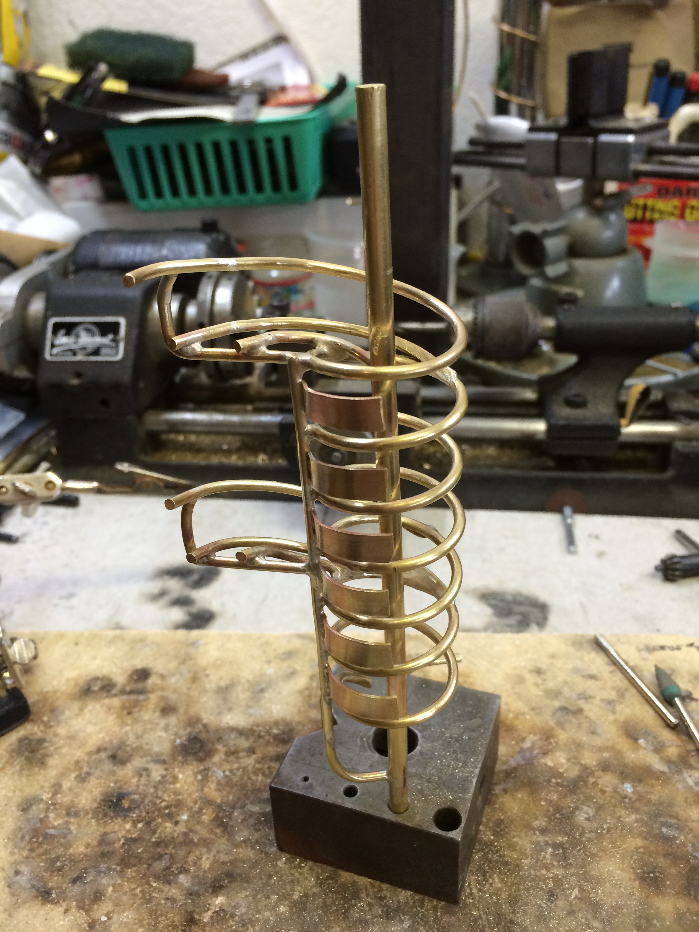
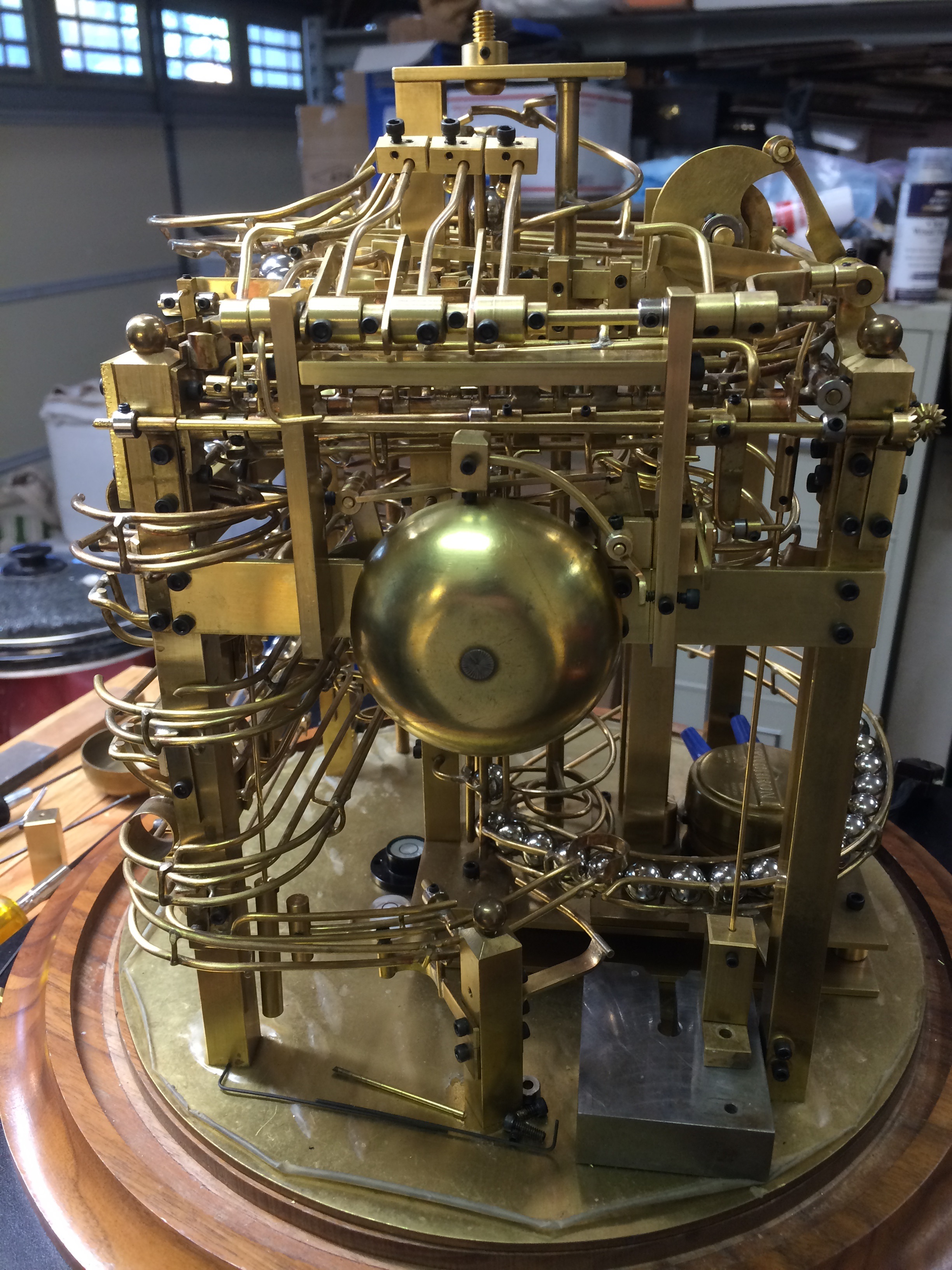
Having completed the quarter ball magazine, it was time to move on to the bell and striking mechanism.

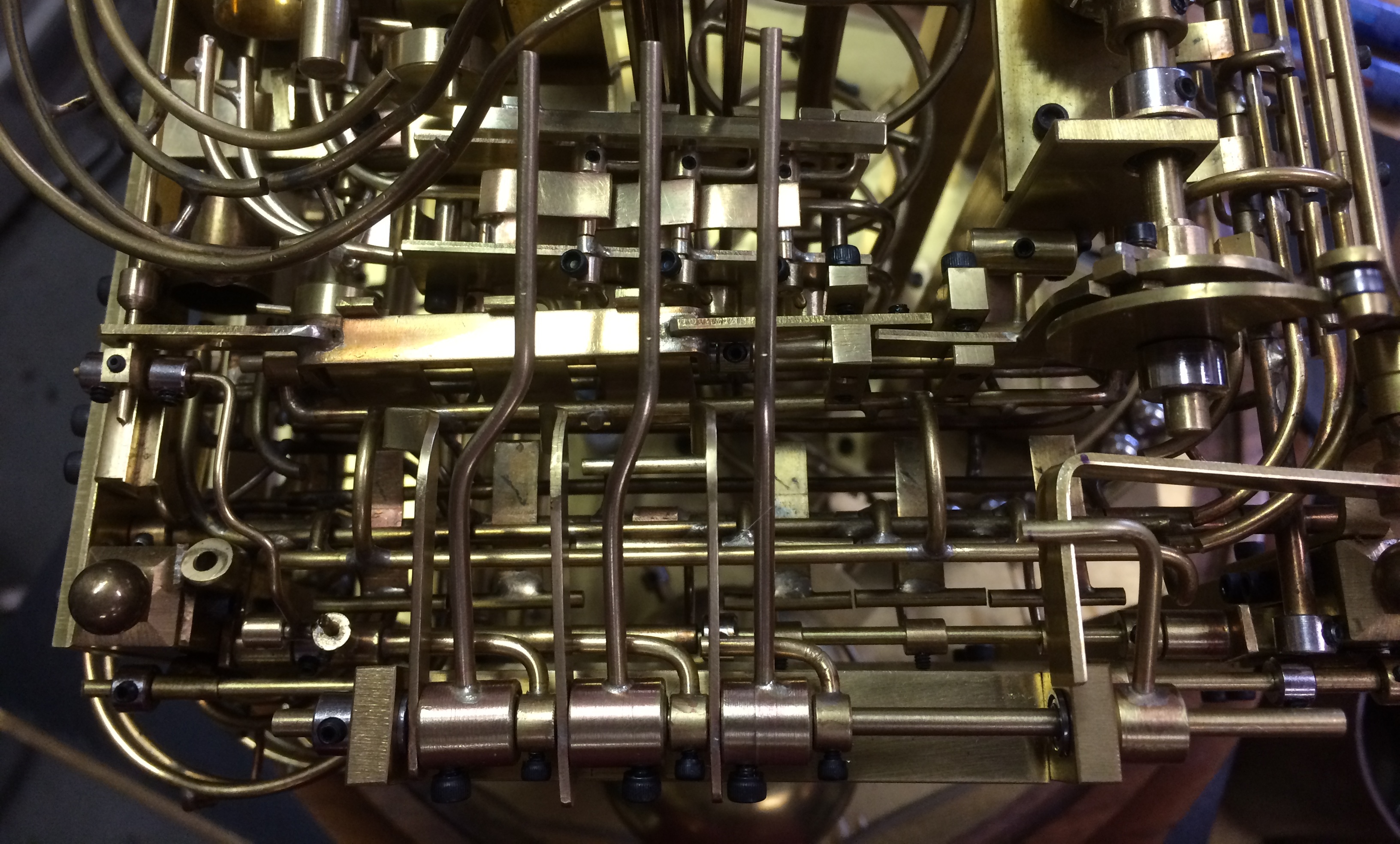
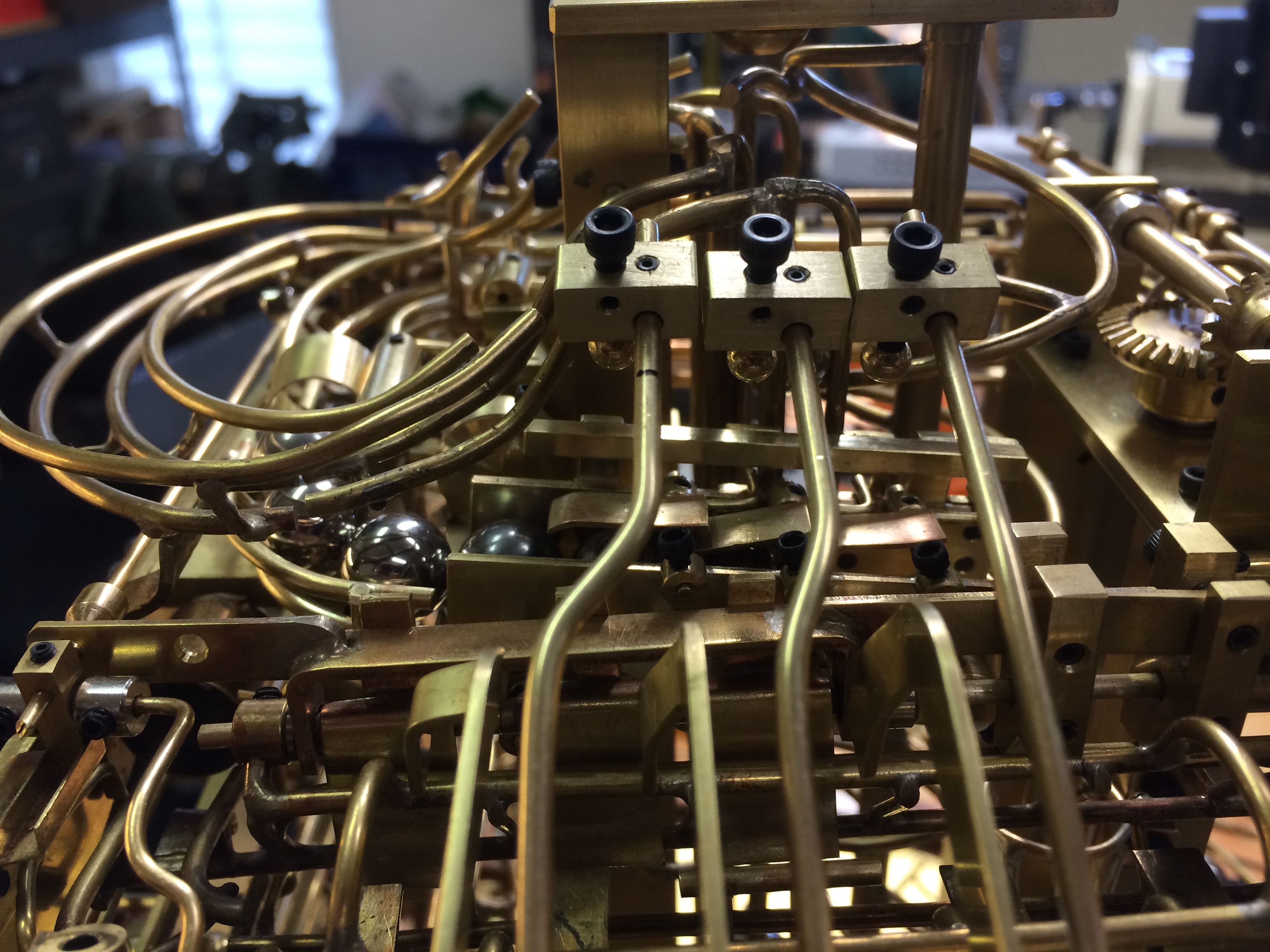
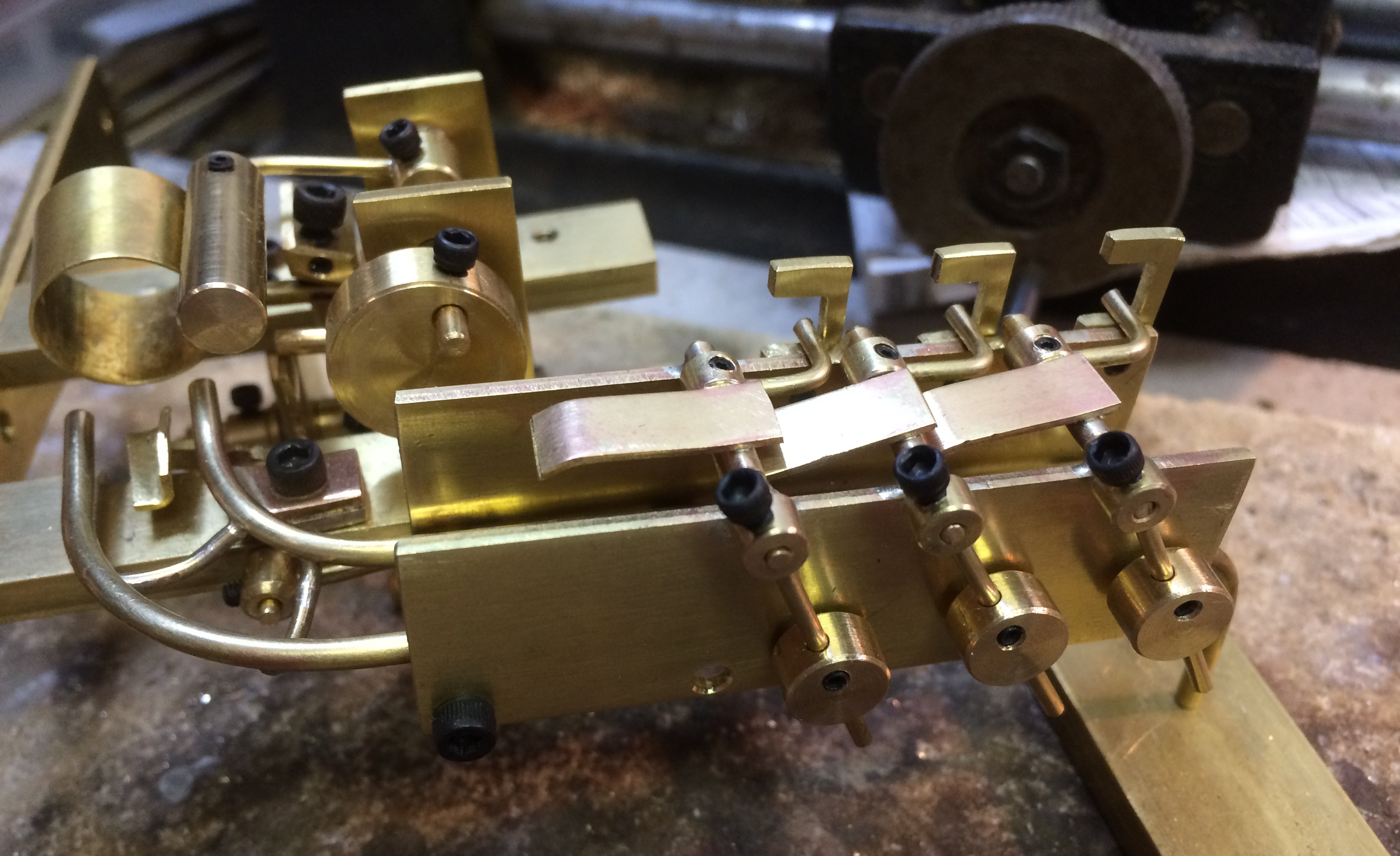
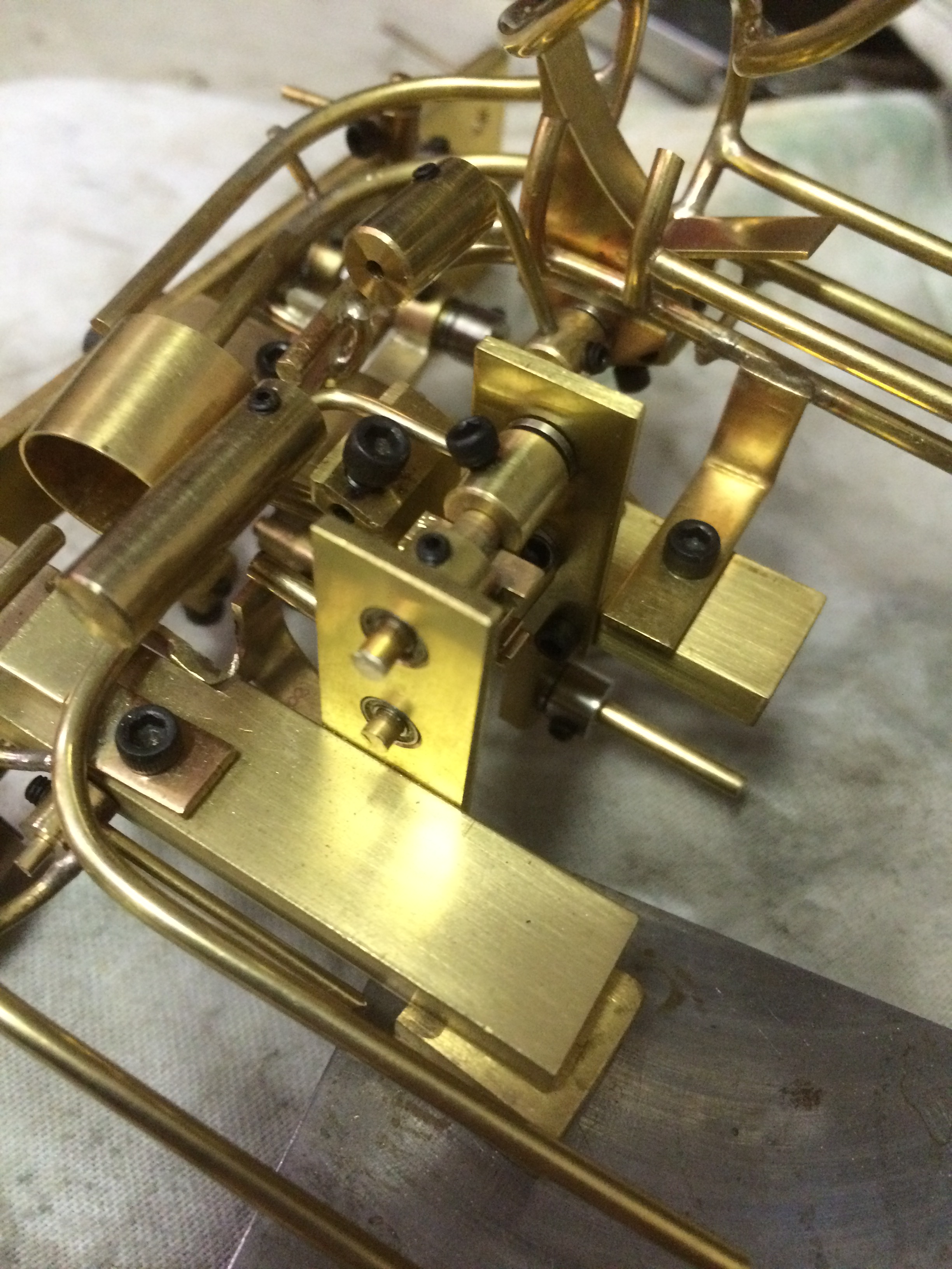
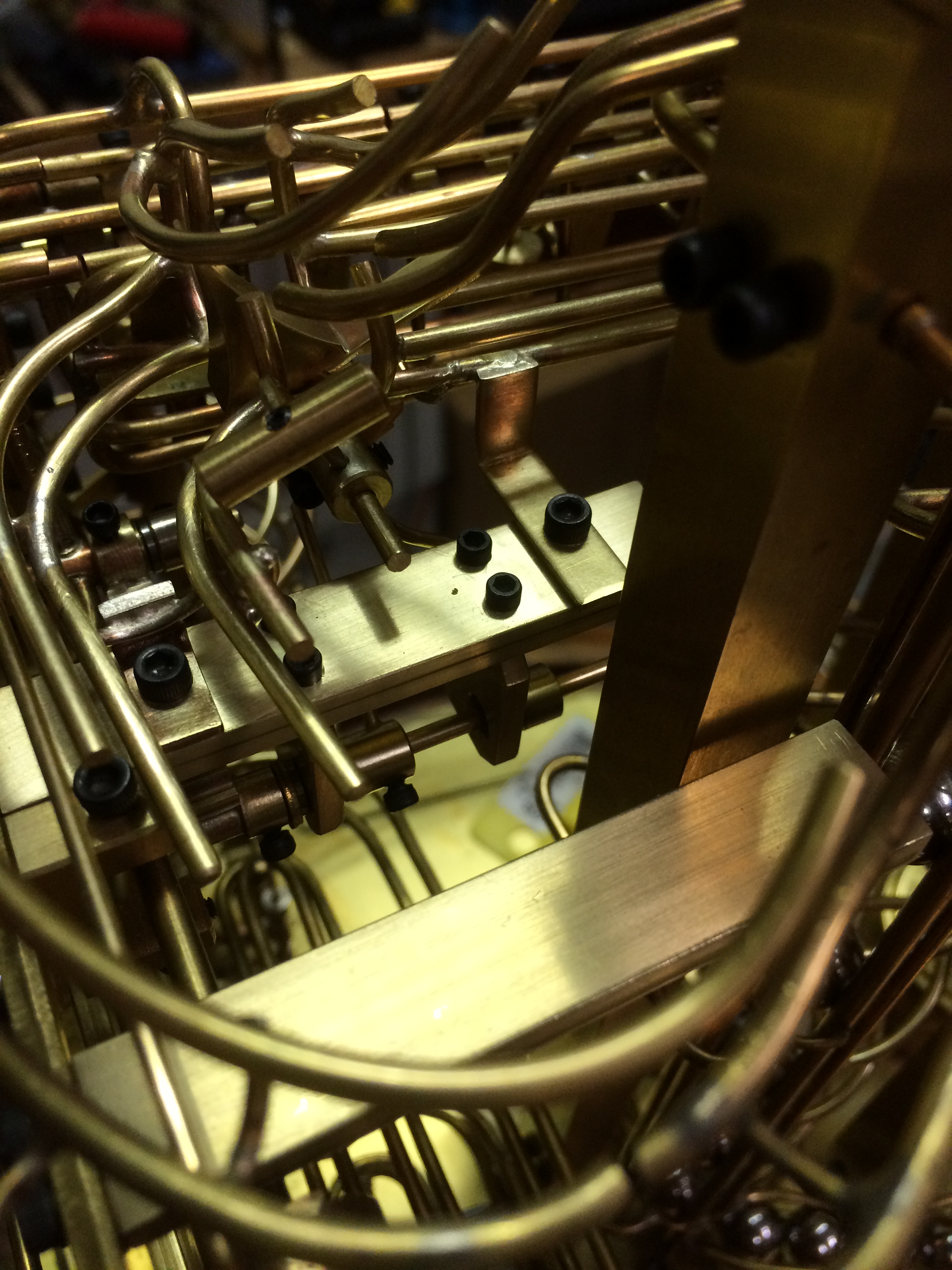
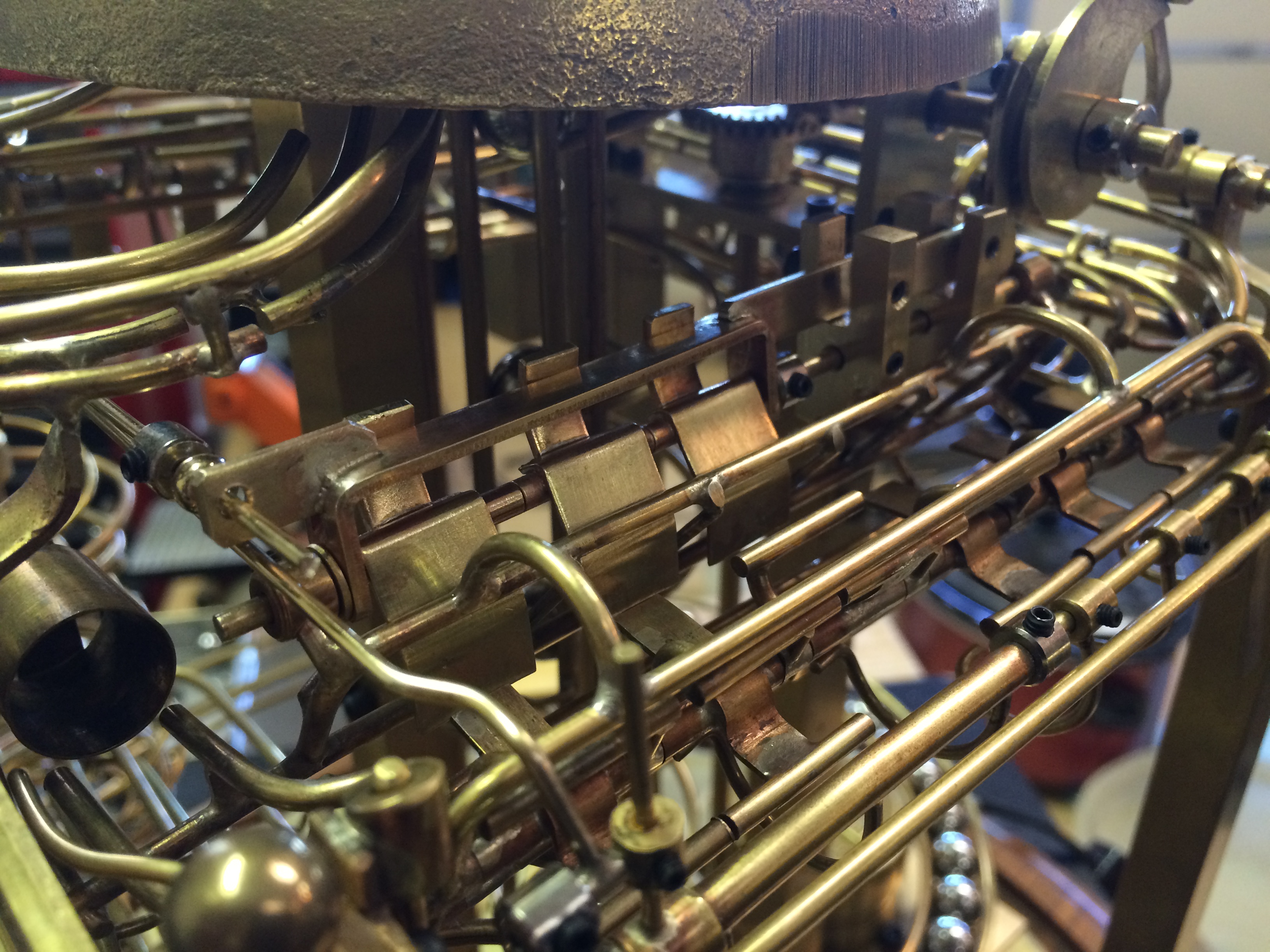
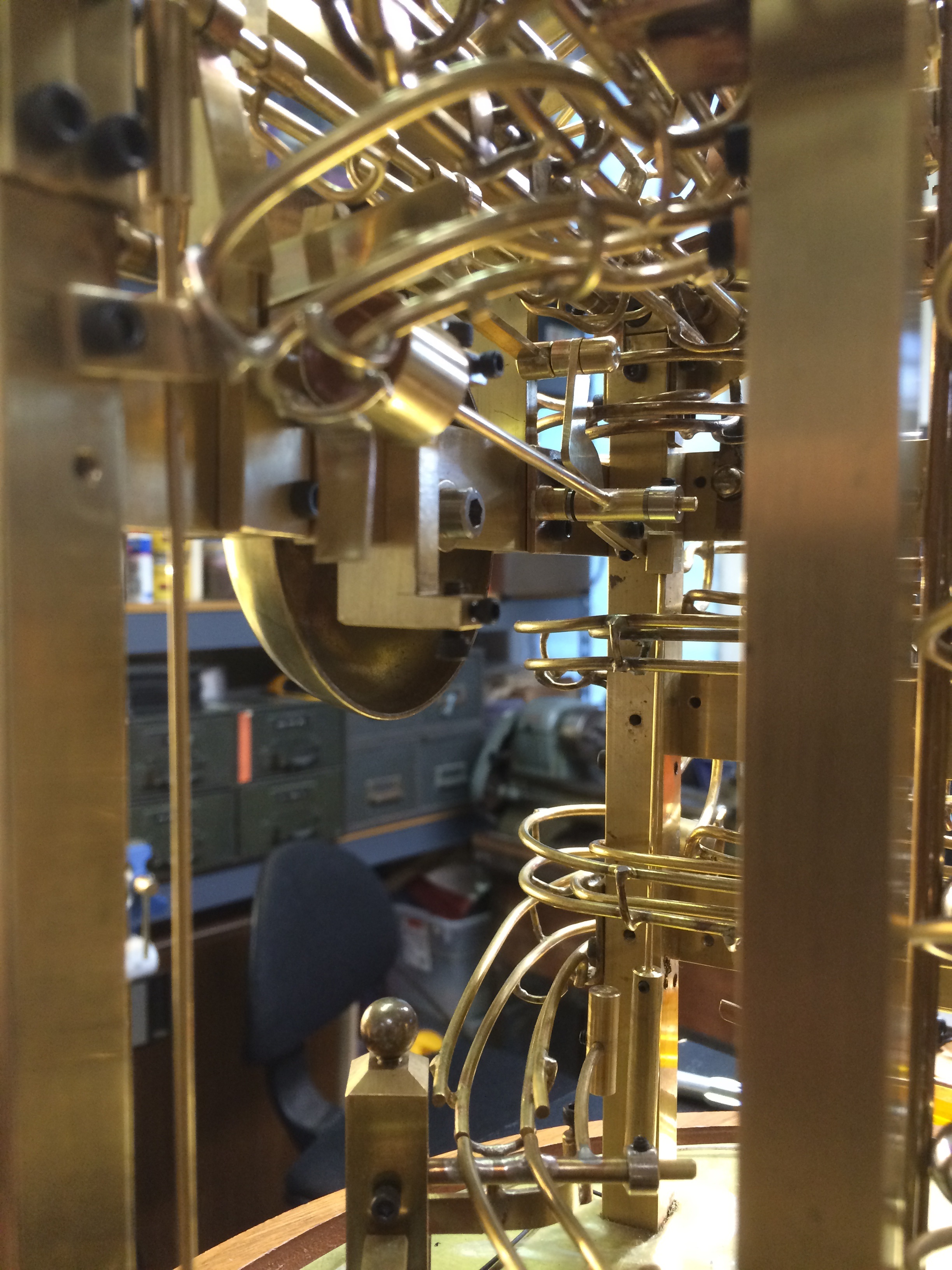
When the balls exit the magazine the drop straight down onto a track that takes them to the level that will use the ball weight to operate the hammer.

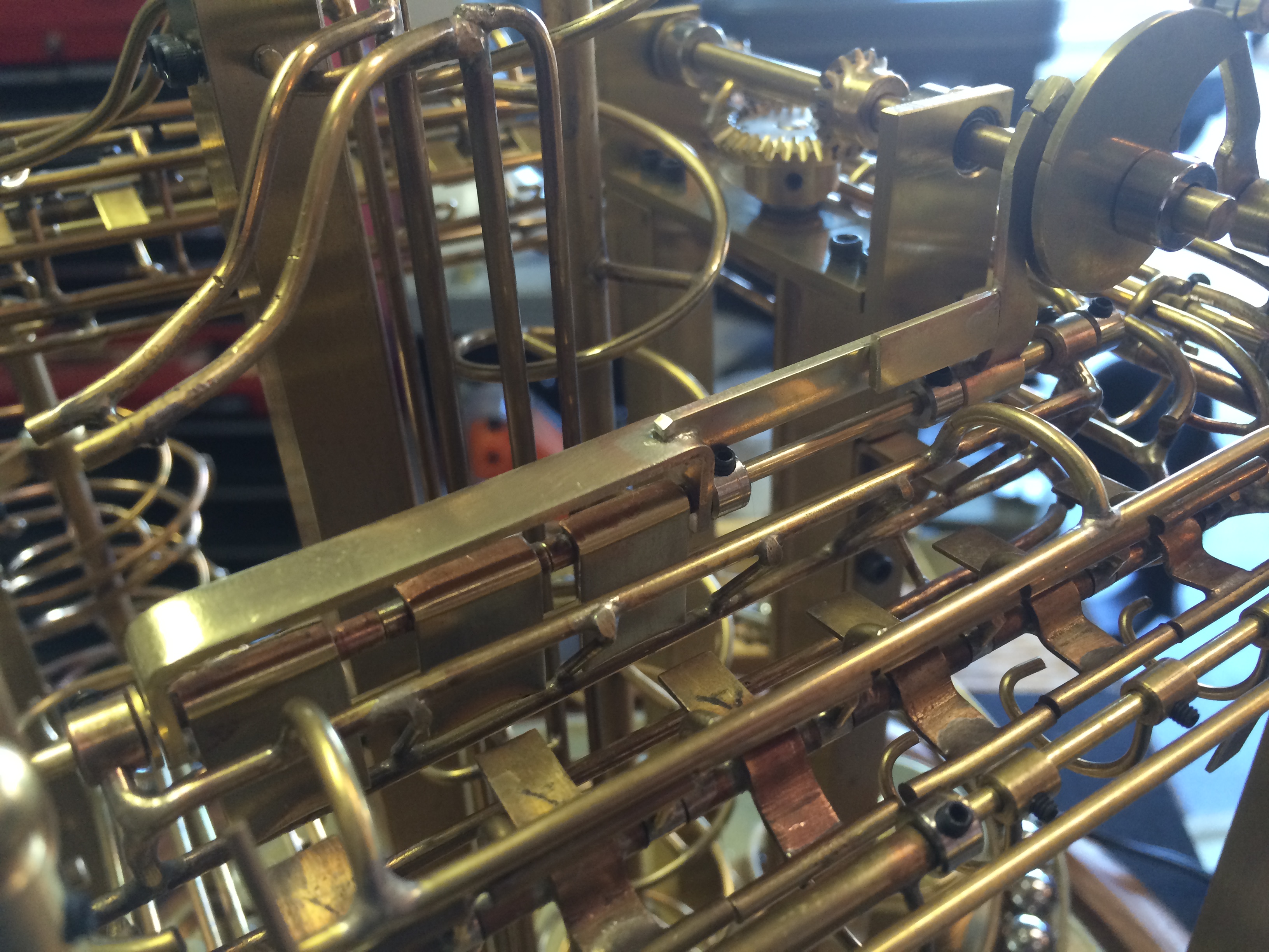
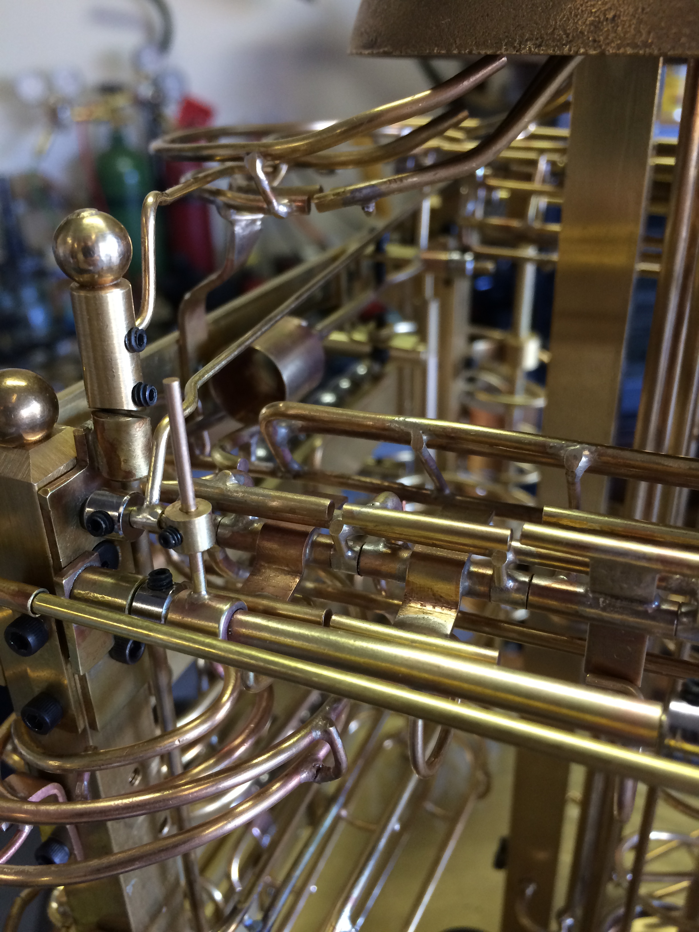
Because there would be multiple balls sometimes, I needed a way to block the balls until a full cycle of the hammer had been completed.

Photo 172
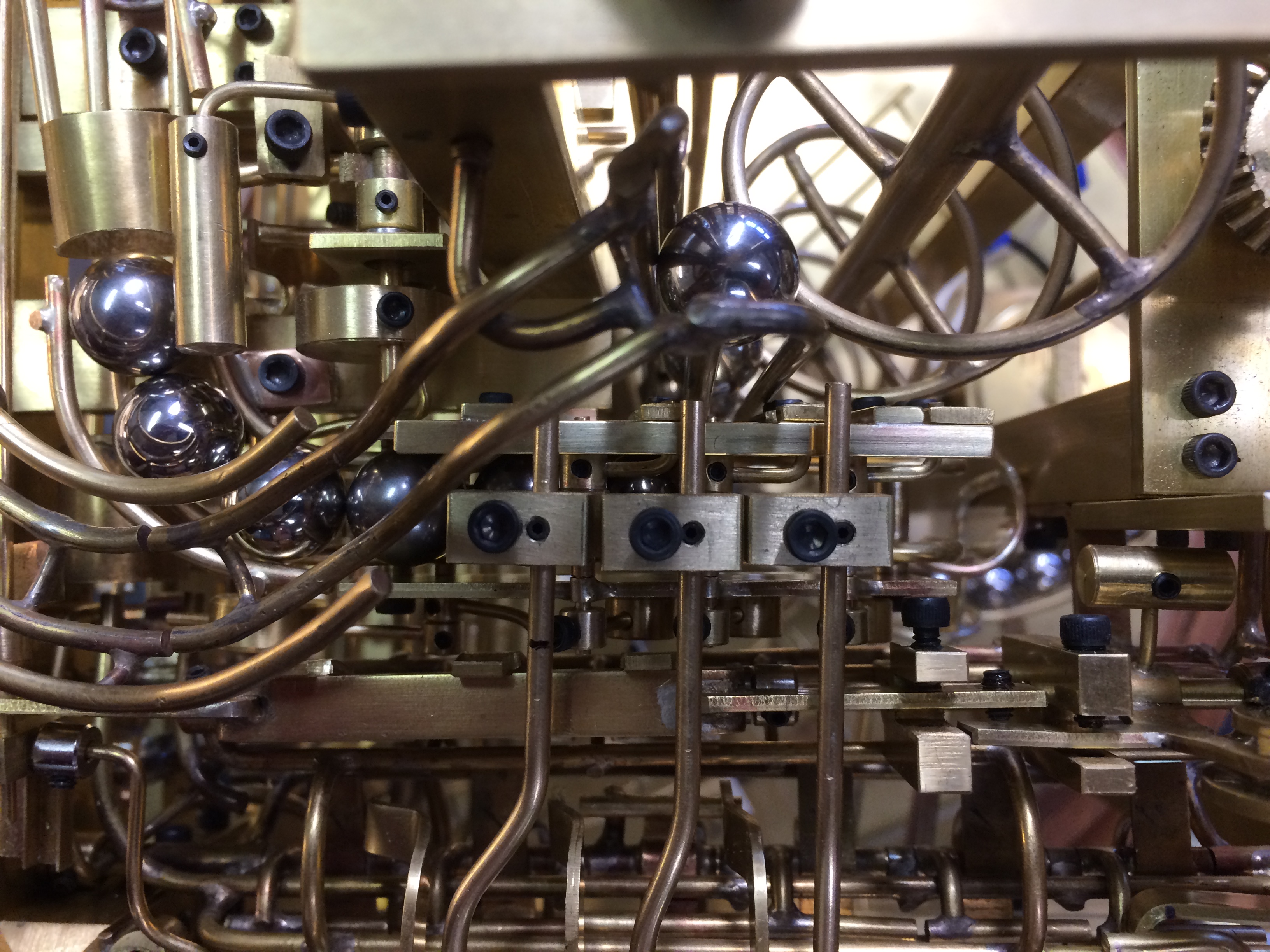
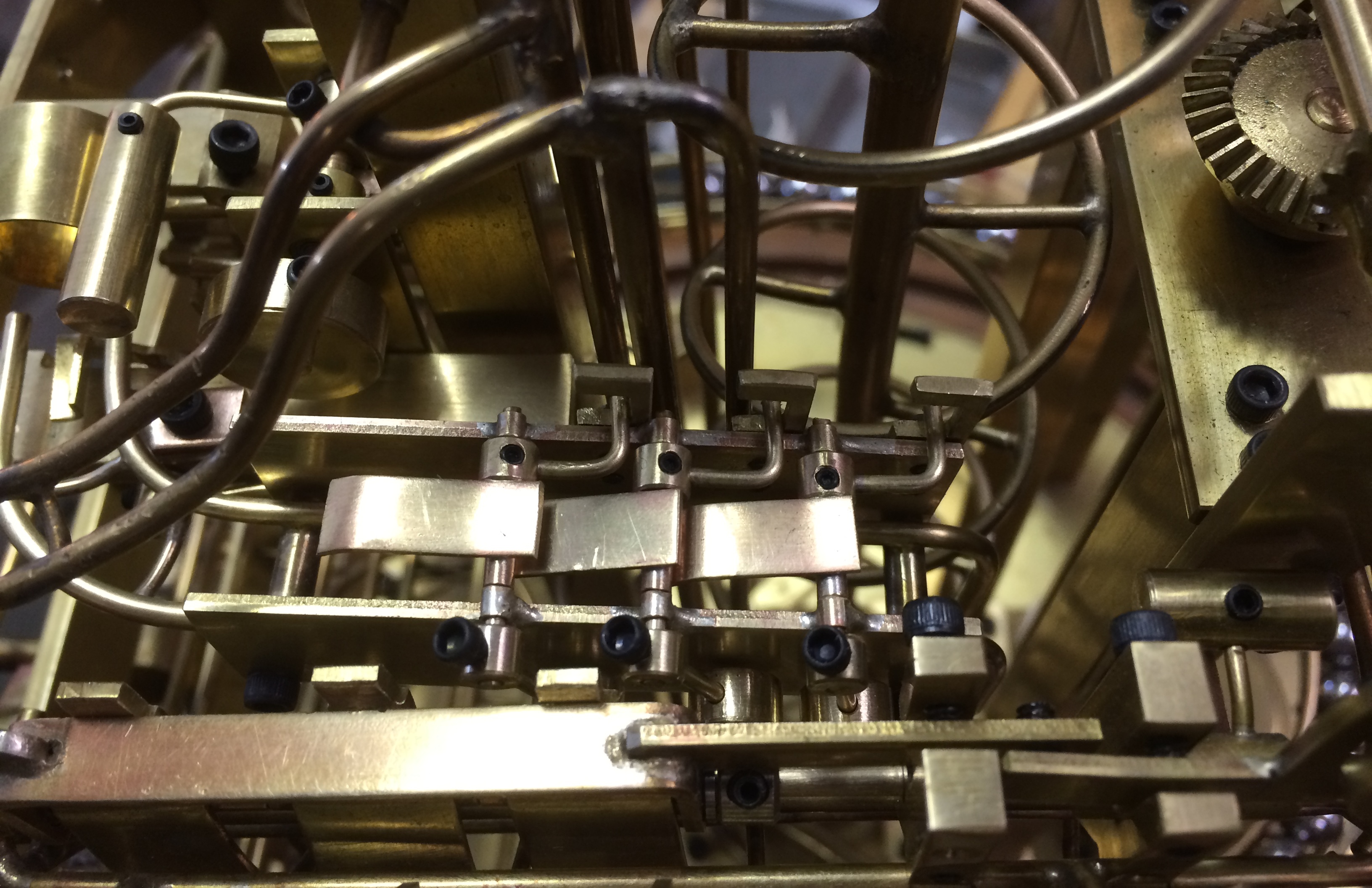
When the ball goes into the cup of the lever, the weight of the ball causes the lever to pivot.  This allows a small flat bar to drop in the path of the rest of the balls.

When the lever returns, it pushes the bar up so that another ball can enter the cup and the cycle starts again.

I noticed that the strike came fast, too fast, so it will require another solution to slow the strike down.

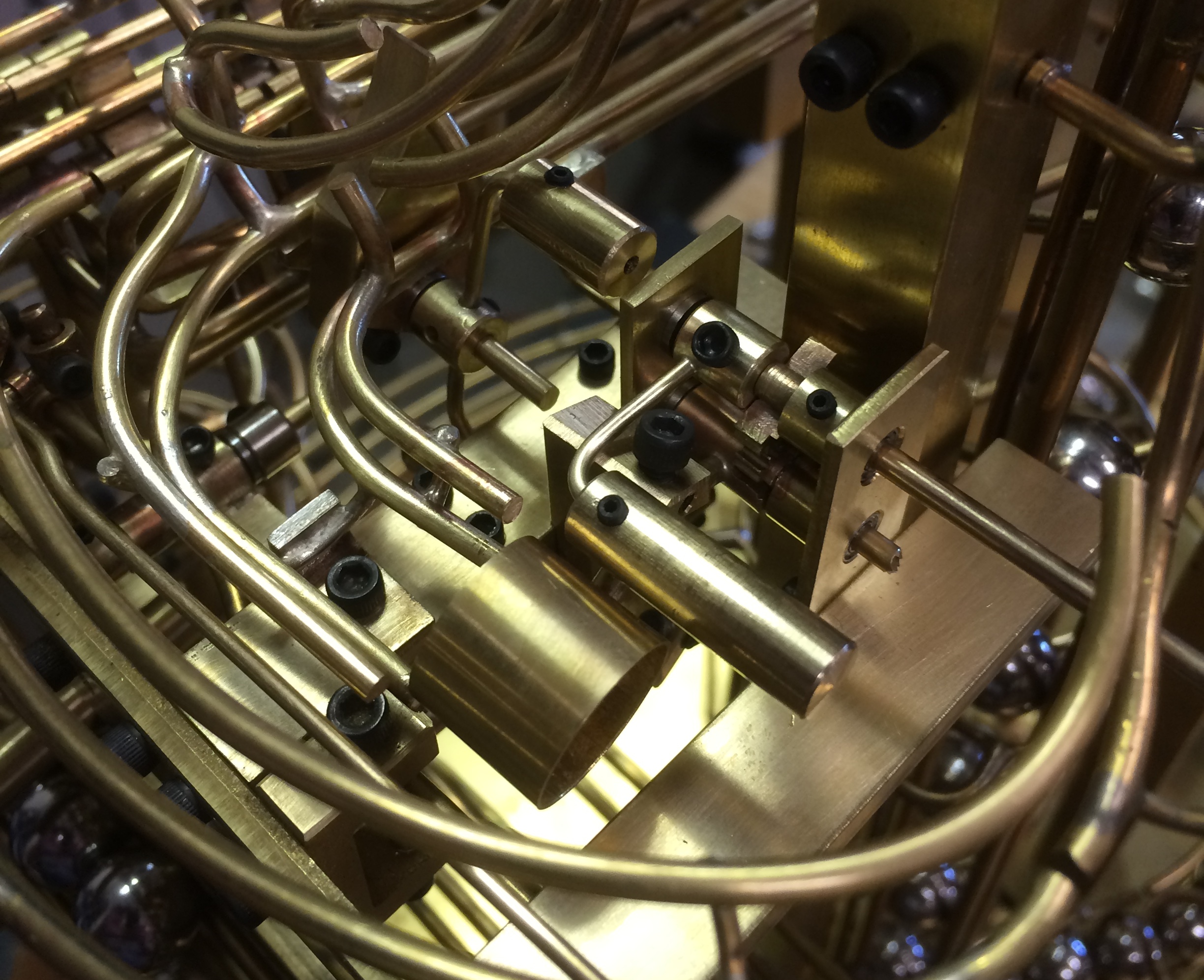
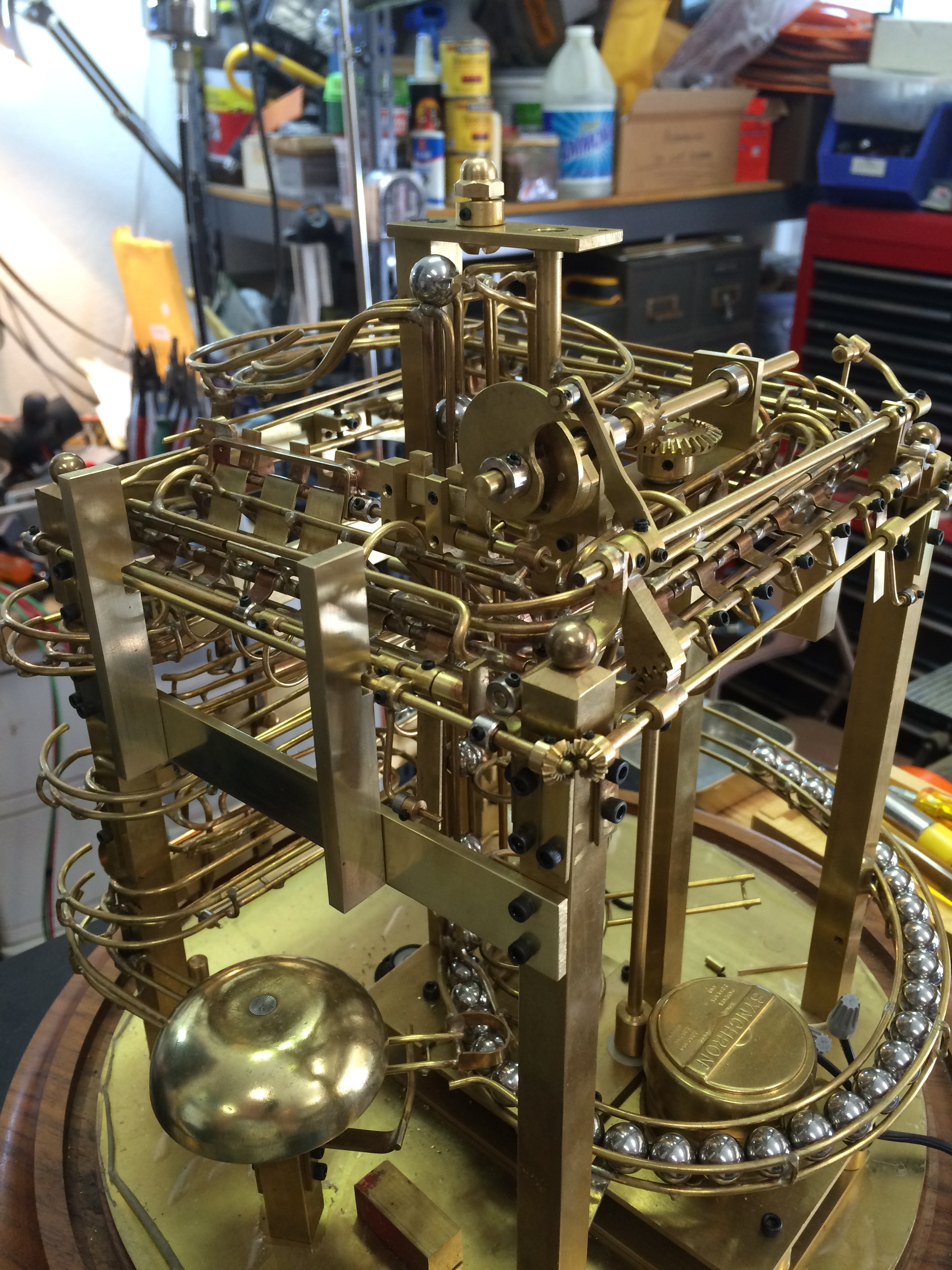
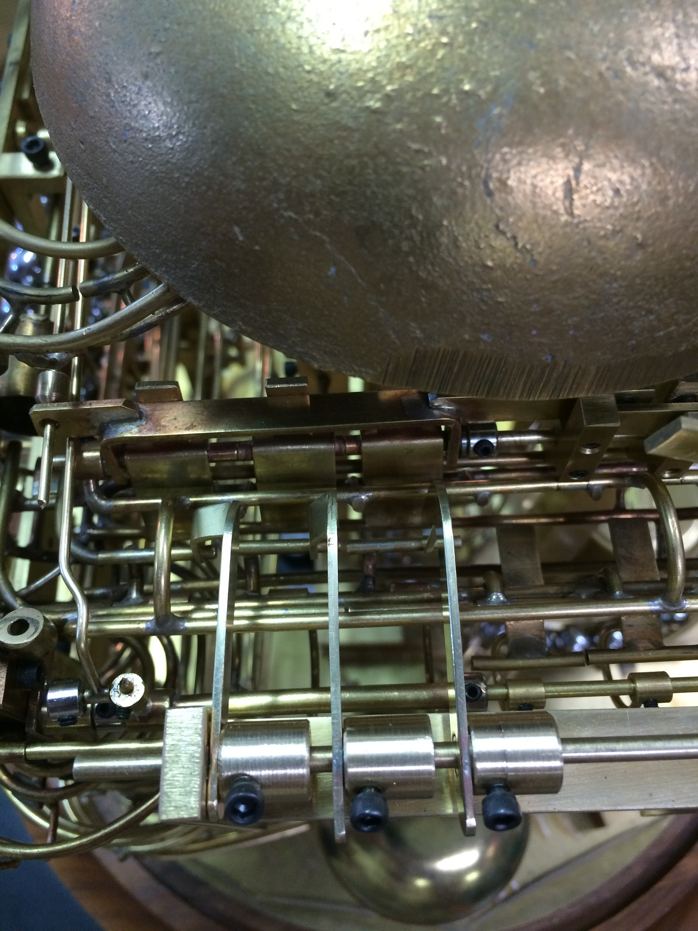
The bell is from a old telephone chime.  I believe from the 1970s.

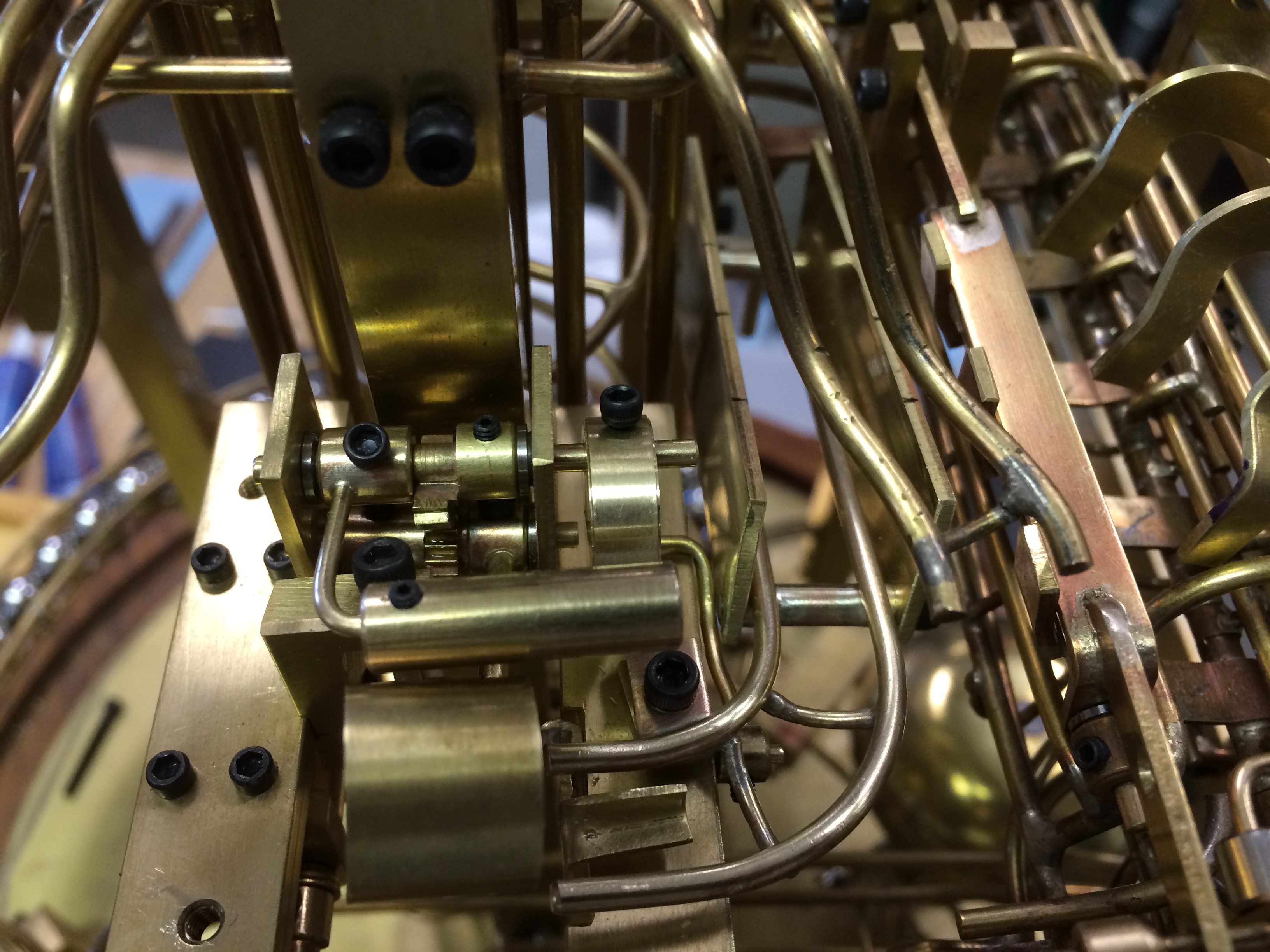
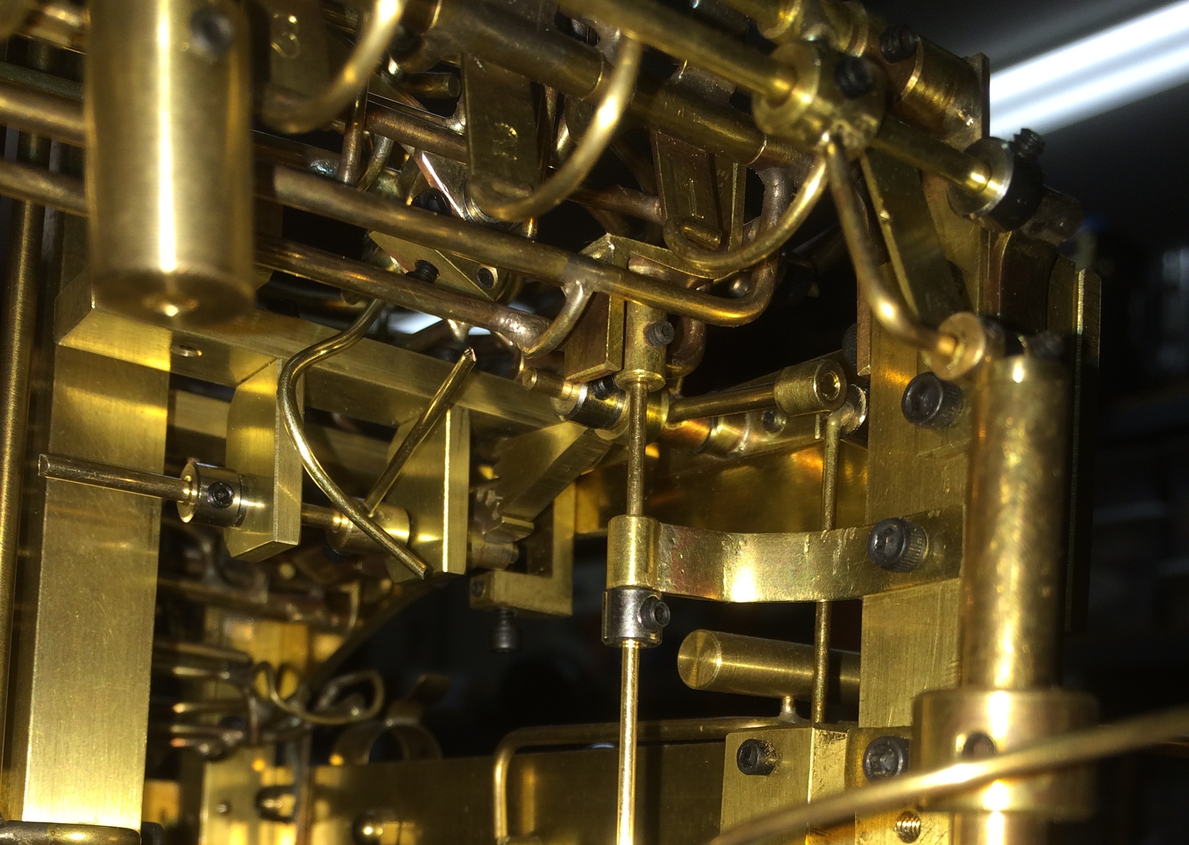
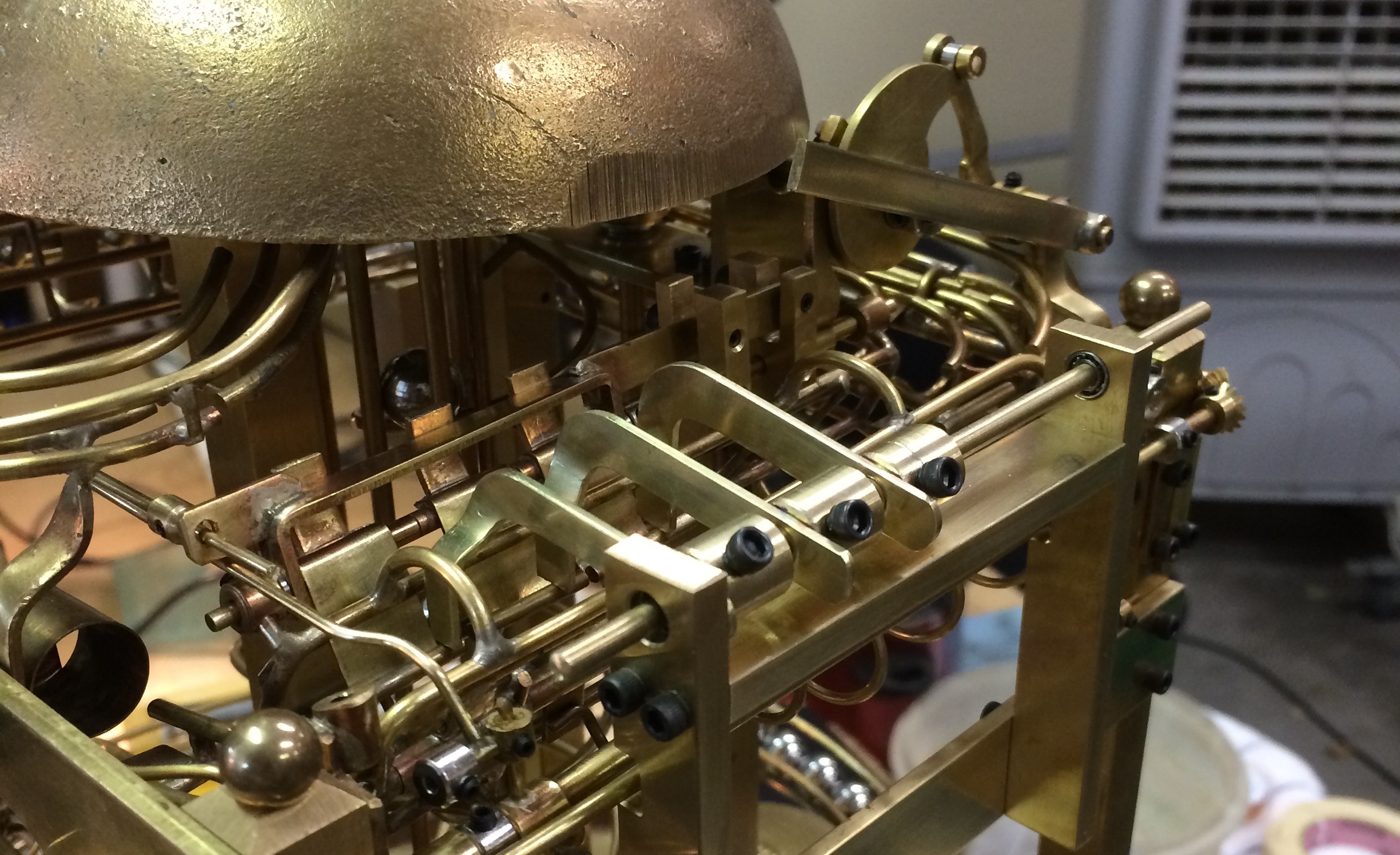
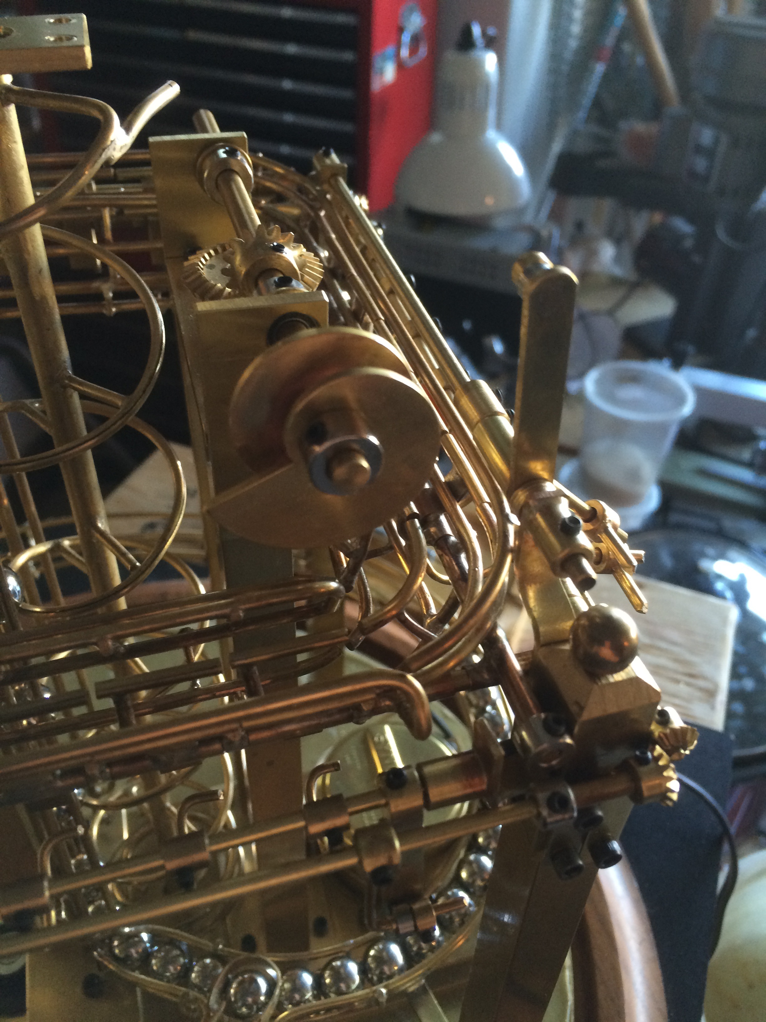
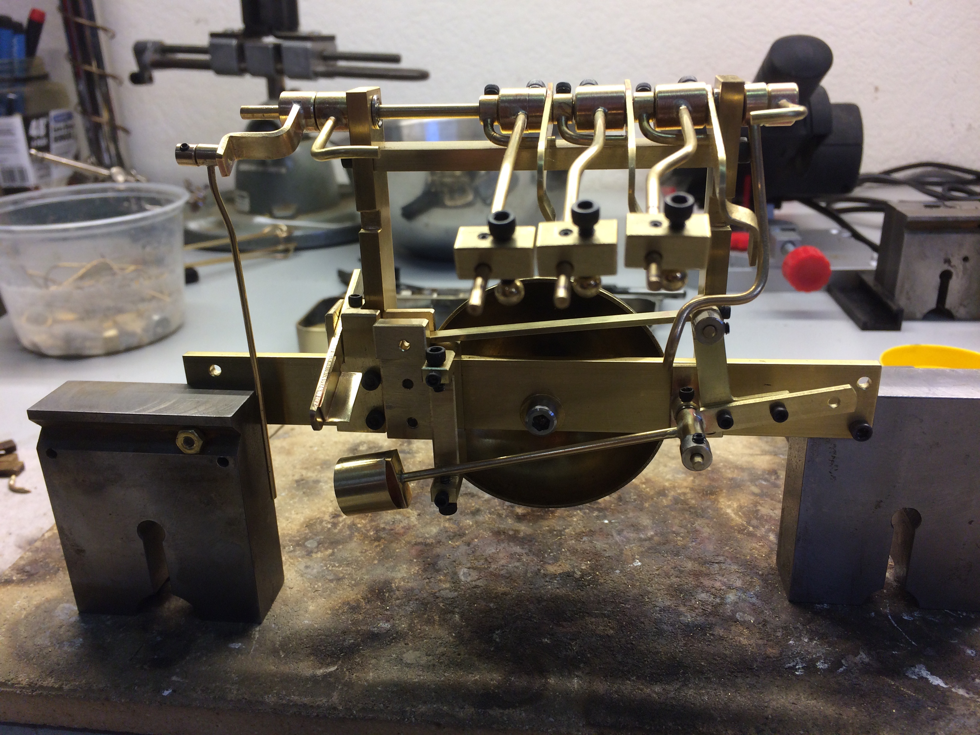
When the level drops it pushes a rod that engages a block attached to the hammer shaft.  The shaft is rotated, the hammer lifted and just before full throw, the rod slips out of the block and allows the hammer to fall.

Photo 170There was a balancing act going on here as the weight of the hammer applies pressure against the weight of the ball powering the lever.

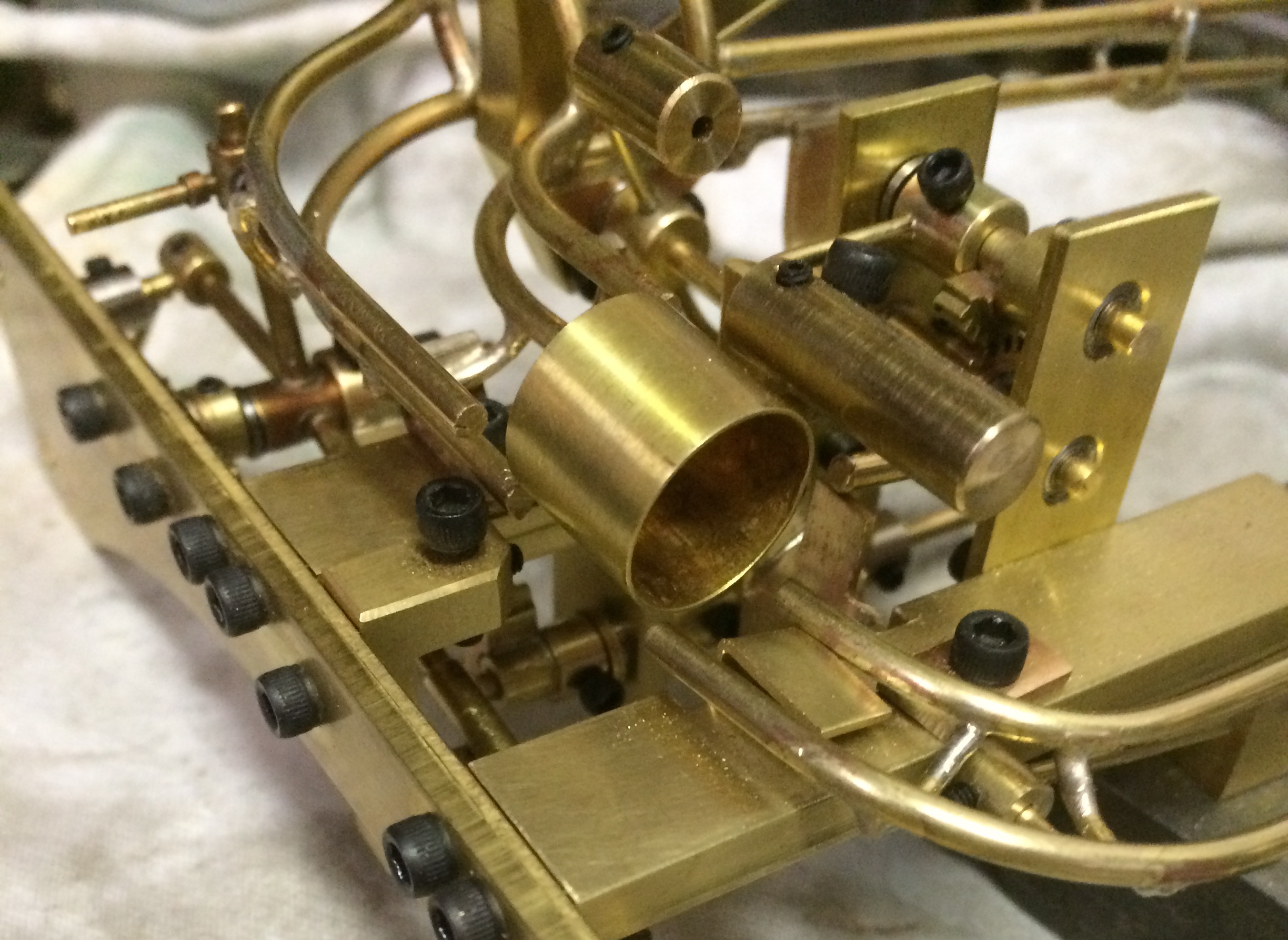
Getting the throw just right took some time.

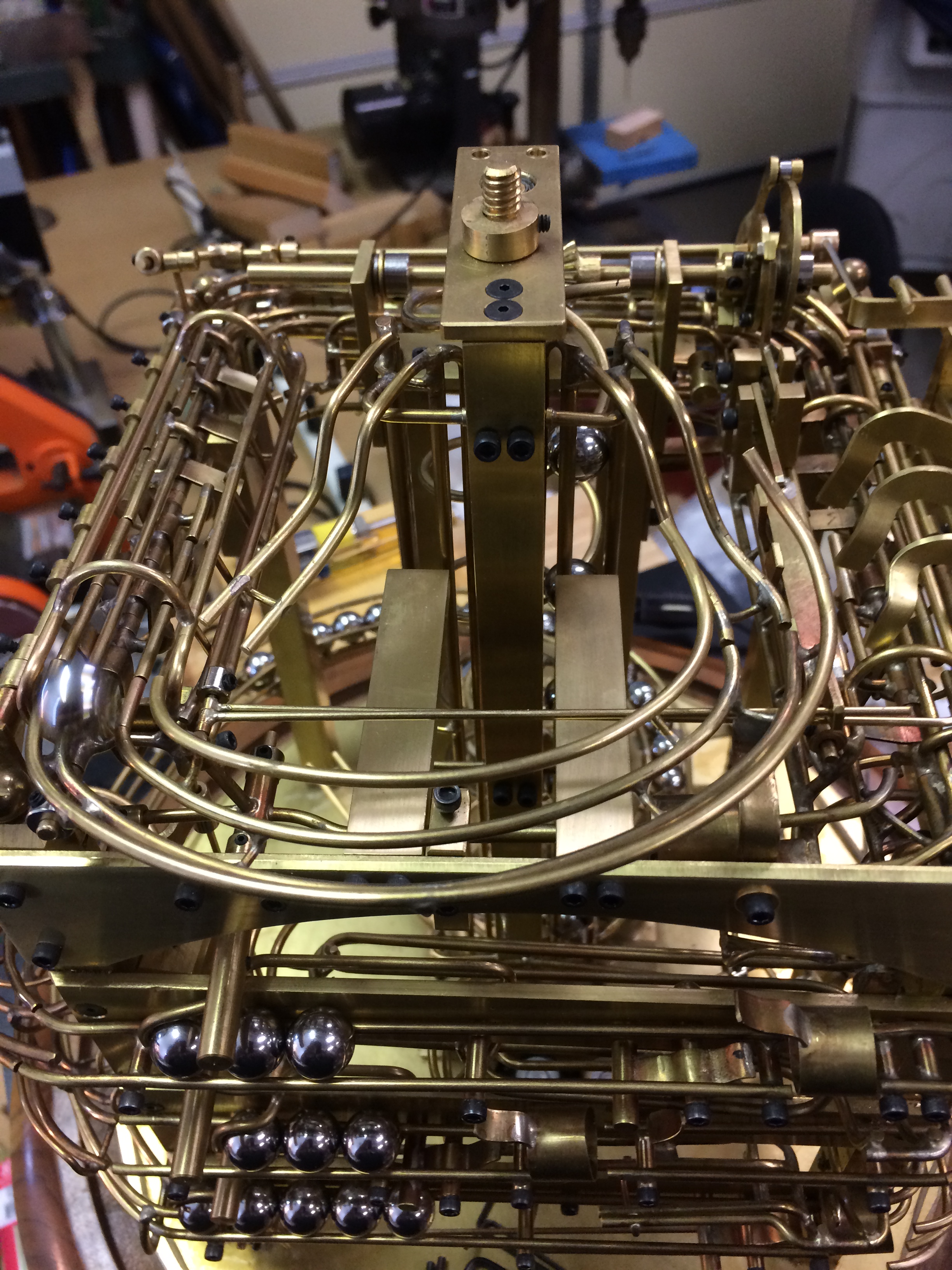
Everything was mounted to the same frame as the feelers so it could be removed as a single unit.

Now to work on dealing with the balls from the striker as well as the ones from the excess drop.


Posted in Ball Clock | Tagged | Comments Off on Ball Clock II ~ Quarter Strike

Ball Clock II ~ Quarter Ball Selection

Photo 158 croppedWith the quarter ball magazine completed it was time to tie it to the feelers for the quarter hour flips.

Rods were attached to the adjustable hubs on each of the feelers.

This way I could adjust the amount of down travel in relationship to the feeler being stopped by the quarter flips.

Photo 162Blocks were also put at the end of the rods to add enough weight to overcome the pressure of the balls releasing.  Screws with small balls at the end allowed for minimum resistance and easy adjustment.

When a ball trips the reset cycle to restore the counter flips it also causes the feelers to drop and sense the position of the quarter flips.  Depending on which ones are flipped, this allows the feelers to travel enough to either block a ball in the quarter ball magazine or allow it to exit.

Photo 161It is important to note that when the full hour ball travels to the end and operated the hour lever, it resets the three flips before the other flips are reset by the clutch cycling the reset shafts.  Therefore when the feelers drop, the three quarter flips are already reset and no quarter balls are released on the hour.

Additional weight had to be added to rotate the feeler shaft when the reset cycle occurred.

Now that I have selected the right number of balls for the quarter strike, it is time to work on the striker mechanism.

Here is a video showing how the selection works.  I added a temporary small section of track just to catch the balls released from the quarter magazine.  Notice three balls were released, which would be the three quarter hour strike.  This is also a good opportunity to see the reset cycle work.  Notice the cam on the upper right.  The balls replenishing the quarter magazine.  I apologize for the roughness of the video, but I couldn’t upload more than 10m.

Posted in Ball Clock | Tagged | Comments Off on Ball Clock II ~ Quarter Ball Selection

Ball Clock II ~ Quarter Strike Magazine

IMG_3949Now that I have a source for balls to replenish the quarter strike magazine, it is time to make it.

Balls coming through the excess ball diverter make a sharp left turn into the magazine. The idea behind the magazine is to separate the number of balls needed for the quarter, half and three quarter strike mechanism.  It needed to be controlled by the feelers that sensed the position of the quarter flips on the time track.

Photo 148 croppedThe magazine is like a small gauntlet with tabs that can come down from the top and stop the balls from passing through.  With counter weights, very little effort is needed to block the movement of the balls.

There is a lower tab that moves away last after the upper ones have had a chance to get into position and also blocks balls outside of the magazine from entering until the others have left.

Photo 155 croppedIt was a tight space, but I was lucky enough to have just enough room.  I guess I need to have a heart-to-heart with the designer… oh wait that’s me so I can’t complain.

Once the magazine is mounted and operational, it is time to extend the feelers so they can operate the selection of the number of balls to release in the magazine.


Posted in Ball Clock | Tagged | Comments Off on Ball Clock II ~ Quarter Strike Magazine

Ball Clock II ~ Excess Balls

Photo 144 CroppedThe last post was for the hour ball.

The second lift delivers a ball to the top about 10 seconds after the minute ball exits.  Running on different paths the second lift provides balls for the striking section.  Also one ball every minute.  The first ball after the hour is diverted to a counter to keep track of the number of balls to release to the hour strike mechanism (Not built yet).

The next balls to come off of the second lift are then routed to replenish the quarter strike magazine (Not built yet) and when full to the hour strike magazine (Not Built Yet) and then when that is full the extra balls will end up in the queue for the second lift.  Sounds simple right?

Photo 146 croppedSo having completed the hour ball diverter, it was time to work on the selector for the quarter strike magazine that would also divert the extra balls.  The area to work in was limited so I had to come up with a vertical solution.

The idea was to let balls pass through the diverter until the quarter strike magazine was filled.  Then the weight of the next ball would cause the diverter to drop down and route that ball to a lower track.  To do this, I had to know when the queue for the quarter strike magazine was full.  A ball coming into the diverter tries to drop, but is stopped by a tab that is in the way until a ball is in the full position of the queue.

Photo 147As long as a ball is in that position of the queue, every following ball will drop through.  It is kind of hard to see, but once again some gearing was applied to make things compact.

The last photo gives a good view of the hour ball diverter in the background.  You can see the tab that causes it to reset when a ball goes through.

Again bearings were used to reduce friction on the parts.

Now for the quarter strike magazine.

Posted in Ball Clock | Tagged | Comments Off on Ball Clock II ~ Excess Balls

Ball Clock II ~ Hour Ball

Photo 124 In the last post I had built the detectors (feelers) for the quarter, half & three quarter hour ball transitions.

When the balls for the full hour travels down the counter, it stays on the high track all the way to the end where it drops into a cup on a lever that resets the three quarter hour flips and starts the reset cycle for the other 14.

It is that movement of the hour lever that I used to add a ball to another counter (not built yet) for the full hour.

I just know that I will need a ball for that purpose and have to plan for it now.

The second lift was built to provide the balls I needed for the strikes and counters.  It is autonomous from the lift for the time keeping side of the clock.

Photo 130 Cropped
The first step was to make a frame to hold the parts for this section.

Two flat bars were mounted to the front brace extending toward the lift and slightly on each side of it.

A track was built with a piece that would flip back and forth diverting the ball coming down from the lift to either the front or the back.

Photo 138 CroppedThe back path eventually will end up in an hour counter of some kind.  The front path will head across and will either replenish the magazine for the quarter strike balls or be diverted away to be used elsewhere.

So when the hour ball causes the hour lever to cycle, it also flips the diverted to send the next ball coming off of the second lift to the back.  I had to gear the shaft to get enough movement to flip the diverter.

When that ball goes through the diverter, it flips it back to allow the following balls to go forward.

Photo 142Simple right?  Well not exactly as it took much longer than I had expected.

Next step is to take care of the excess balls once the quarter ball magazine, (not made yet) is filled.

I’m kind of making this up as I go.


Posted in Ball Clock | Tagged | Comments Off on Ball Clock II ~ Hour Ball

Ball Clock II ~ 15, 30 & 45 Detectors

IMG_3837 Photo 121 Cropped Photo 122When I first started out building the clock, I knew I wanted to be able to strike the quarter, half and three quarter hour.  When making the counter section, the last three flips were dedicated to this function.

The idea here is to strike once for quarter, twice for half and three times for three quarter hour on a smaller dedicated bell.  The hour strike will be a separate operation and use the big bell on top.

The plan was that every fifteenth ball would be counted by one of these flips or trigger the hour cycle.  That working, there needed to be a way to detect how many were flipped so that the appropriate number of balls could be released into the striking mechanism.  (Not built yet)

My only indication was the position of the flips after the ball had passed.  If you remember, the balls that went through this section would trigger a clutch and reset the other 14 flips.  I decided to use that same cycle to operate some arms that would feel the position of these three flips. The first photo give a good look at the clutch arm and how it is geared to the reset shafts.  The ratio is about 3-1 so I get good rotation of the reset shaft with little movement from the clutch arm.

First a frame was made to hold the feelers and eventually the bell and striker.  It was made in such a way that it could be easily be removed from the rest of the clock.

Next came the 3 feelers.  When tripped, they would be stopped short by flips still in the reset position and allowed to travel more where they had been tripped.  They follow the cycle of the reset lines for the rest of the flips.

Obviously they will have to do more than just cycle, but one thing at a time.

Now that I can detect the 15, 30 & 45 minute passing, I need some balls to select for the striker.

This is where the second lift rail comes in.

Posted in Ball Clock | Tagged | Comments Off on Ball Clock II ~ 15, 30 & 45 Detectors

Ball Clock II ~ Reset Clutch

Photo 096To utilize the aux power shaft, I had to be able to control when the reset of the flips occurred.

There had to be some sort of a clutch to engage the reset cam on the shaft.  This is getting complicated.

The reset of the flips had to occur every 15 minutes at the quarter, half, three quarter and full hour.

The trigger for these events had to come from a ball dropping thru the appropriate flip.

There had to be a way to detect that happening and set off the reset cycle for the 14 flips.  Also the same had to occur at the full hour where all 17 flips would be reset.

Photo 101I created a bail that was moved when a ball contacted a flat plate adjacent to the flips.  The bail would move a pawl away from the clutch dog and allow it to engage the power shaft.  The pawl had to move back into position to stop the clutch on the next rotation allowing only one cycle of the reset shafts to occur.

The trick was to provide enough travel from the ball dropping to the exit path and still not get stuck while passing through.

Photo 109It became a balancing act to reset the bail and still trip the clutch.

In the lower photo you can see a rod going through a hole in a tab on the bail.

The rod is operated by the hours lever and will trip the clutch for the full hour reset.

Now time for some detecting.


Posted in Ball Clock | Tagged | Comments Off on Ball Clock II ~ Reset Clutch

Ball Clock II ~ Hiccup

Photo 071Not everything on a project like this can go as planned it seems, especially when you make things up as you go along;  I have had to remake a few pieces that didn’t quite work out the way I had planned.

For the last two months, every now and then, I would get a ball jam in the exit spiral.  The clock would run for a few days straight and then I would see balls jammed in the spiral.  Each time it happened I would try to figure out what and how it had happened.  It appeared that when the minute rack dumped (9 balls) and the 10s of minutes dumped (5 balls), there were times that the balls would collide in the spiral.  I attributed this to a lack of smoothness of the minutes balls running down the spiral and not clearing a path for the 10s of minutes balls in time.

So, I tried modifying the spiral with flat strips of brass to make a smoother travel down for the balls.  That worked to make things run faster, but did not completely alleviate the jamming, which occurred now maybe once a week.  Rats!

A closer look by taking a slow motion movie, showed that the balls on a upper turn would rub against the balls just below them, allowing them to jam against one another and slow the decent.

It was time to take a new approach and remake the spiral.

Photo 090This time I did not make it as tight and made sure that the balls could not touch each other vertically from one loop to another.

This also sped up the balls going down the spiral, gave good separation between the minutes ball dump and the tens ball dump, plus created a good aesthetic in the process.

The downside is it took about 16 hours to make the new one.

The lovely thing about physics is that you cannot ignore it.  If it happens once…it will happen again as it is really only a matter of time.

I suppose that is true with a lot of things in life as well.  Sometimes you just have to “bite the bullet” so to speak and just do it!

Now, back to the Aux Power.


Posted in Ball Clock | Tagged | 1 Comment

Ball Clock II ~ Aux Power Shaft

Photo 085After completing the reset shafts for the track flips, it became obvious that I needed extra power to drive the reset shafts.

When making the main drive train I left an extra shaft available on the top of the gear box.  This shaft turns at 2.5 rpm as the drive train ends up turning the main lift spiral 1 rpm.  Remember the lift spiral releases one ball every minute.

The idea is to make an assemble that is serviceable and removable from the main gear assembly, so that it can be easily modified as the project progresses without disturbing the main drive.

I decided to use the same 1/2″ square bars as I did with the main columns for support and aesthetics.  A lower plate was attached for mounting the columns and an upper plate for a housing a bearing and bracing for the horizontal shaft.  The drive shaft is 3/16″ diameter brass rod.

Photo 087The upper assembly has two (Boston) gears to achieve a 5 rpm of the horizontal shaft.  I figured that would give me five opportunities to do something every minute.

Bearings were installed at all points of the assembly.

The trick was to just fit the top of this below the main bell and still have room for power takeoff.  I ran the horizontal shaft long in both directions, so if needed it would be there.

The movie shows the beginning of a cam/clutch assembly that will be used to reset the flips.  I still have to convert that movement into operating the reset shafts.

Now the next step is to use the power.

Posted in Ball Clock | Tagged | Comments Off on Ball Clock II ~ Aux Power Shaft

Ball Clock II ~ Hour Reset

Photo 078Up to this point I only had the balls that traveled around the counter just route to the racks without really doing anything.  Once all of the flips have created a track around and back to the front it would be one hour.  I needed to reset the 15, 30 & 45 minute flips to start the count again.

Only one time during the hour would the ball roll across the 45 minute flip on its way to the minute rack.  I decided to use the power from that ball dropping to the exit track to reset the 15, 30 & 45 minute flips.  For this I needed a way to capture the ball in a cup and have it operate a lever.  I also had to keep the ball captured until the lever had made the full travel.

To conserve the energy, I put bearings in the pivot axel of the lever.  A counter weight was added to return the lever after the ball had exited the cup.

Photo 077I linked the lever to the reset shaft to reset the three flips every time the ball would end up in the cup.

Originally I thought I could reset all of the flips with ball weight, but soon discovered that that would not work.  There just wasn’t enough power to move the three reset shafts full cycle.  Something else would have to be done to power the reset of the other 14 flips.

Also shown in the photos is the reset arm for the 1 o’clock ball release.  The idea was to have the next minute ball move the arm and release the latch holding the captive 1 o’clock ball on the hours rack.

Now to find some power for the reset.


Posted in Ball Clock | Tagged | Comments Off on Ball Clock II ~ Hour Reset