Now that the balls are transitioning through the hour lever, the next things to do are provide an exit path for the balls and to harness the power from the lever.
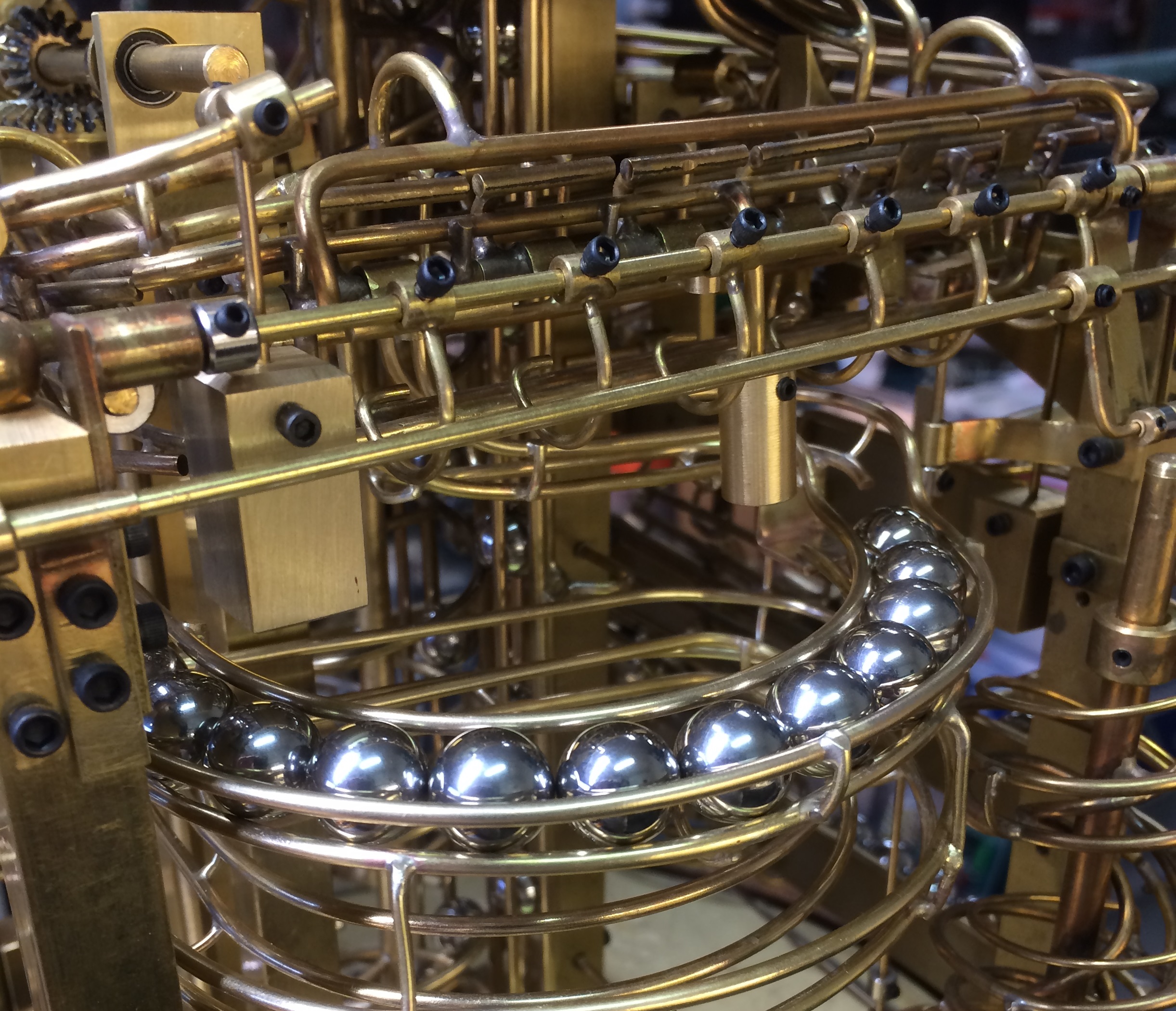
Since there was already a track that went by the lower level of the travel of the hour lever, (Ok that was a weird sentence) I decided to divert the balls to it.
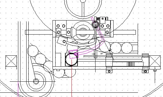
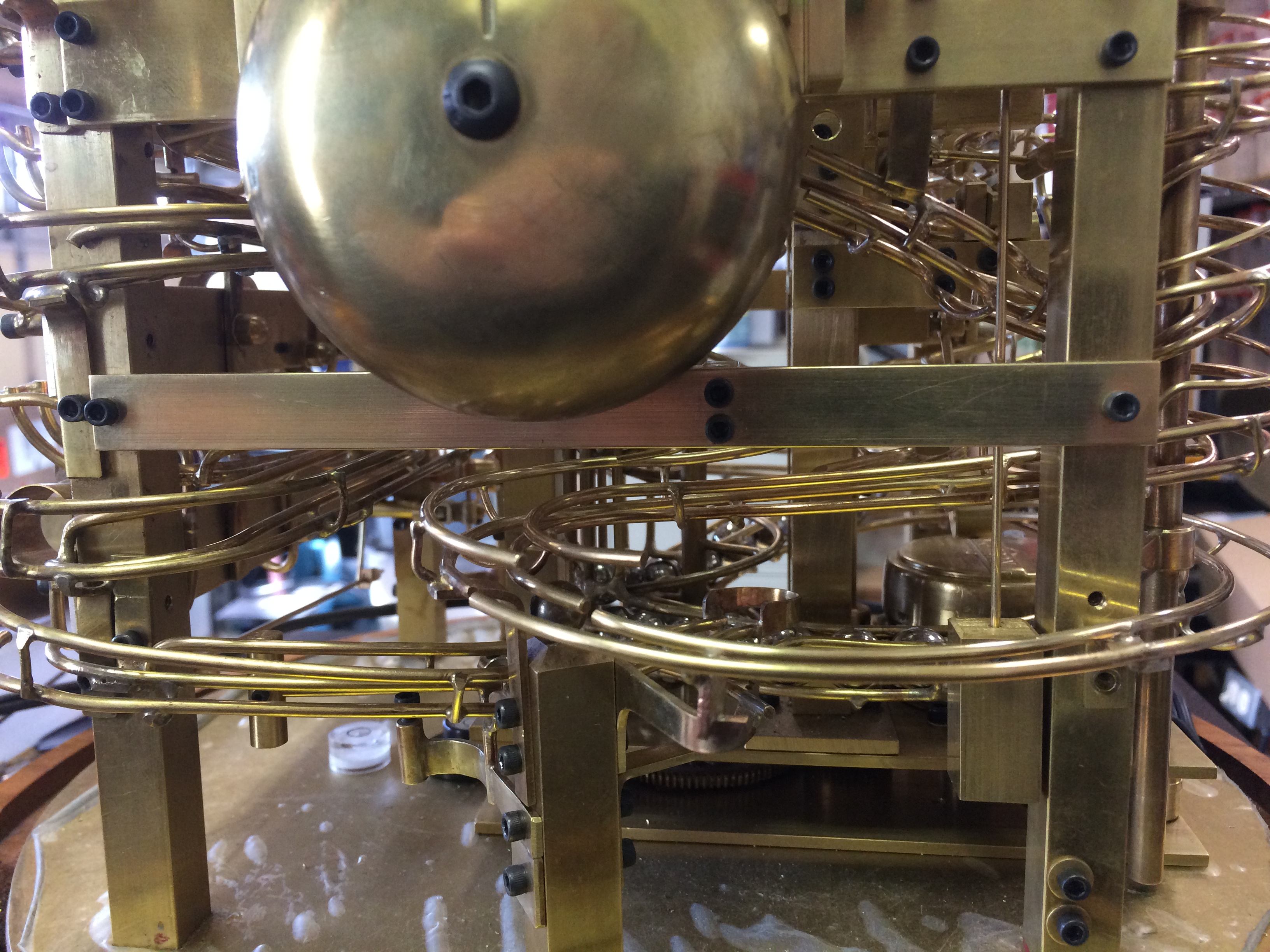
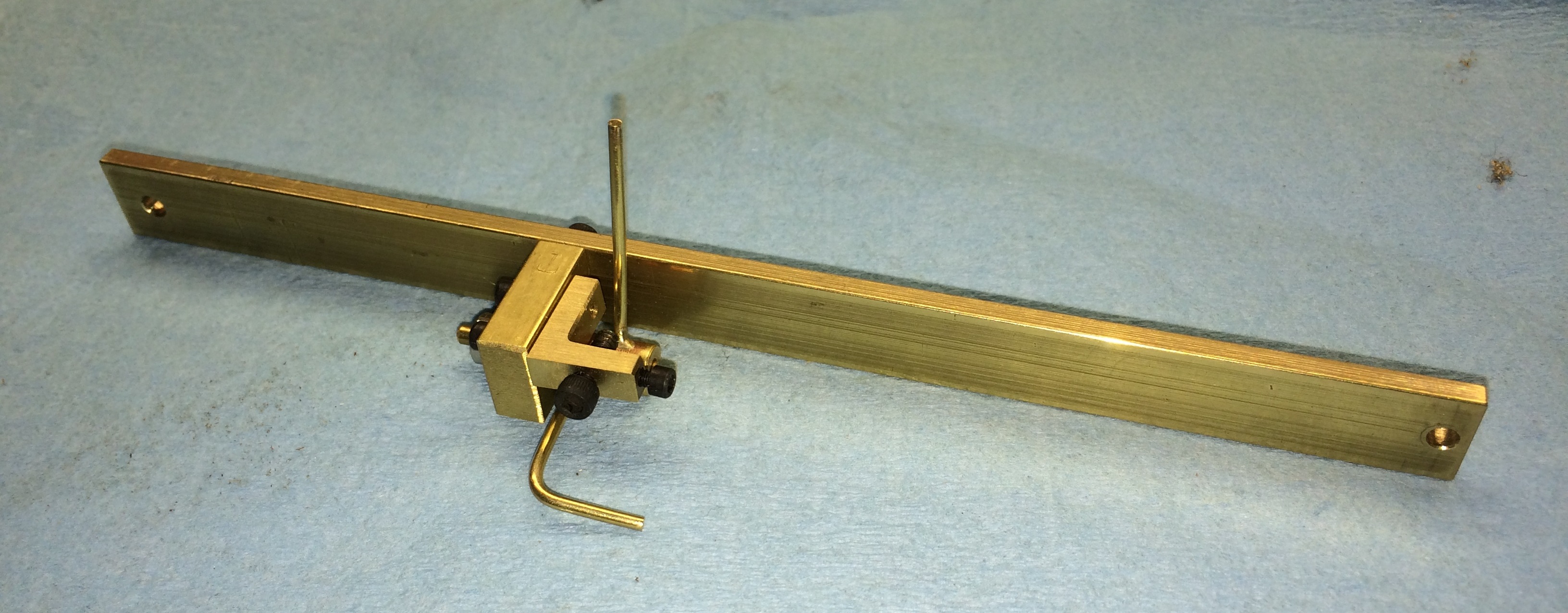
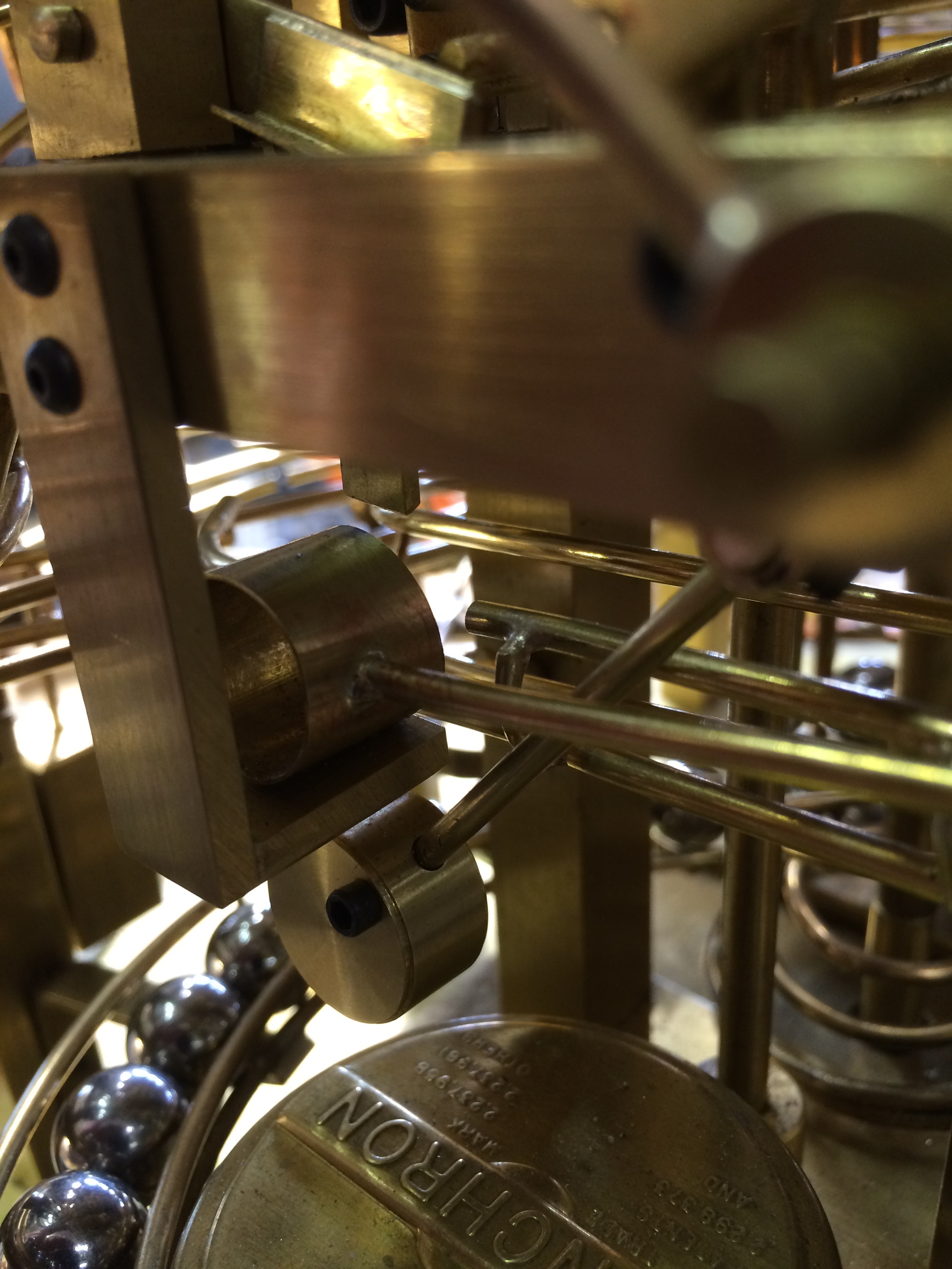
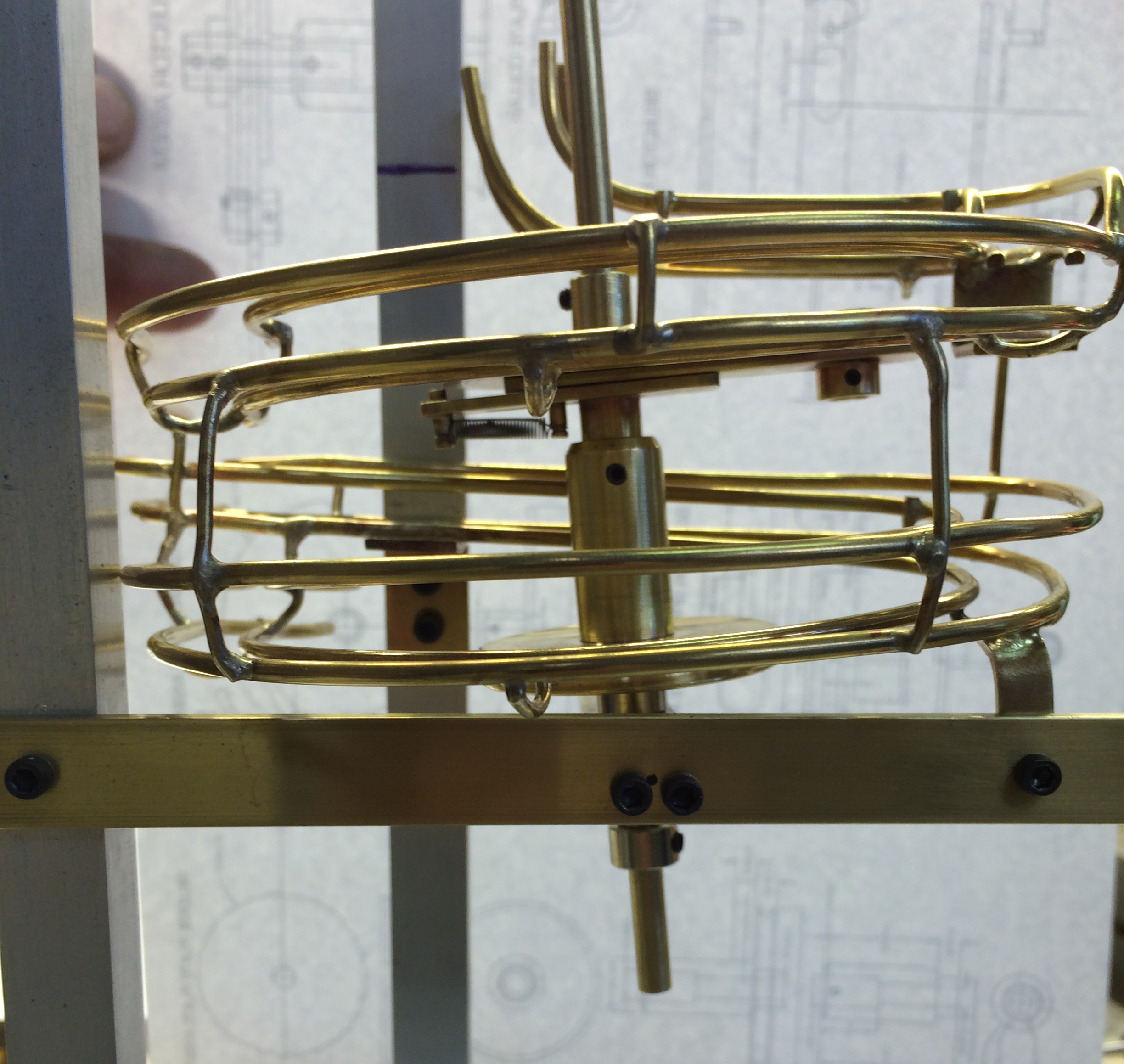
A bracket was made to provide a stop for the hour lever and also divert the balls to the back track. (see photo) The photo shows the hour lever cup in the down position.
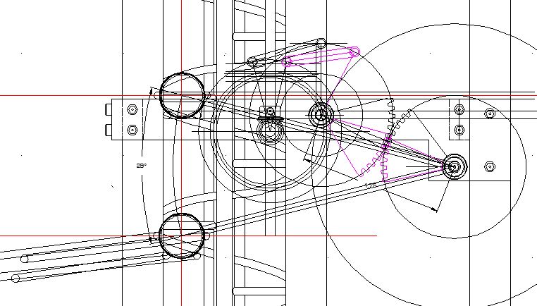
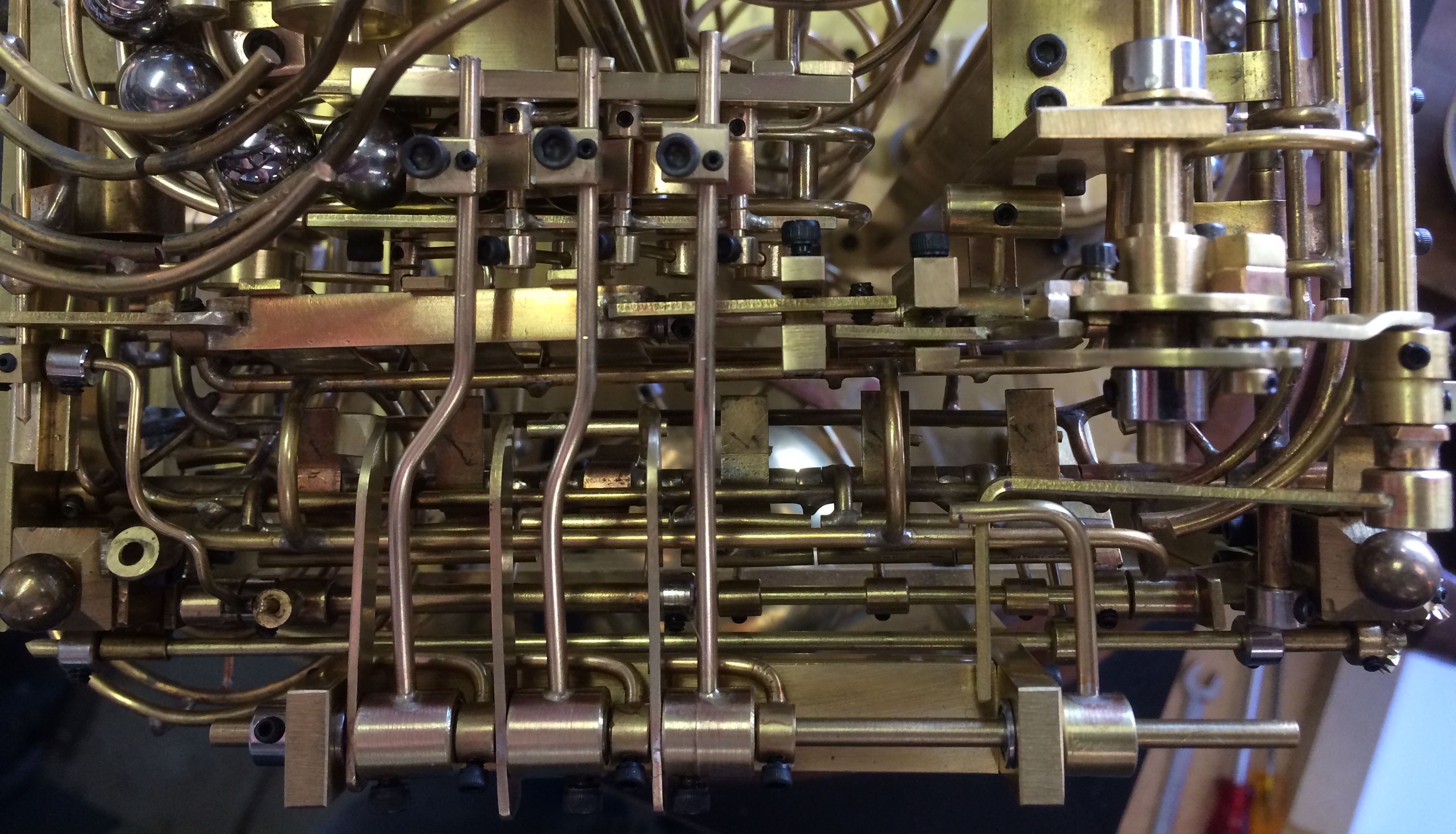
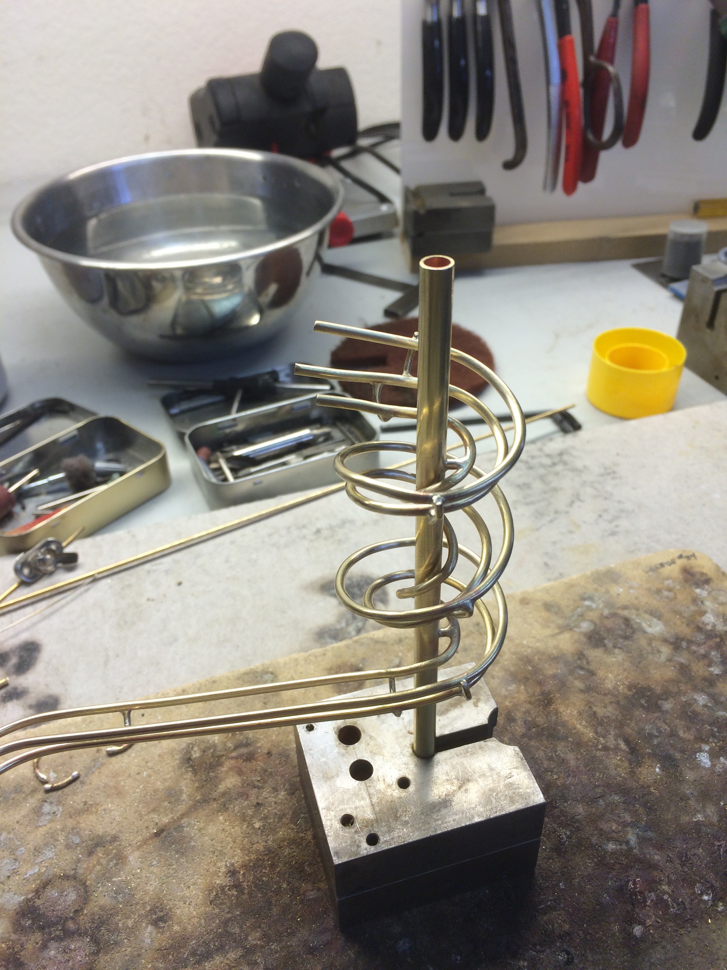
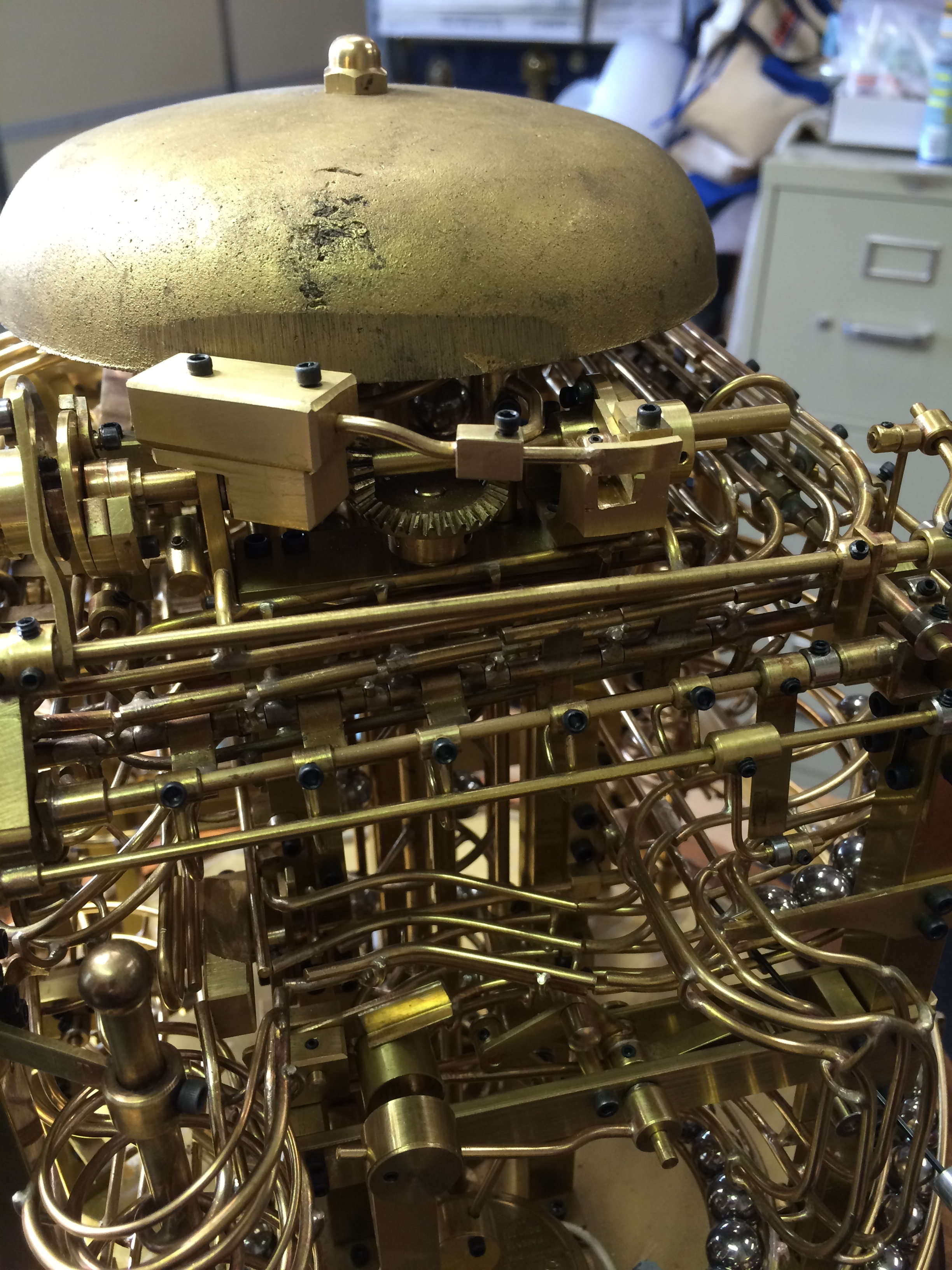
To get the power from the hour lever up to the top, I made a bevel gear assembly (see photo) and mounted it to one of the vertical columns.
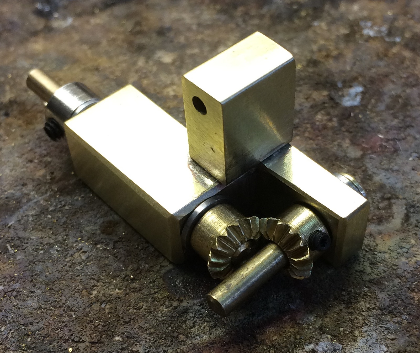 Ball bearings were installed to insure a smooth operation of the gears. A rod then carried the movement from the lever assembly up to a hammer by the bell.
When the weight of the ball carries the hour lever down, the vertical rod will rotate cocking the hammer.
When the ball exits the cup, the lever returns up allowing the hammer to strike the bell. That is the theory anyway.
 I quickly learned that I needed more power to make the bell louder. The only way to accomplish without starting all over was to add more weight to the hammer. Since the hammer rotates horizontally, it didn’t affect the hour lever very much.
However, there was an erratic timing of the strike as the balls transitioned through the lever mechanism and what I felt was just too fast. I needed a way of pacing the strike so it could easily be counted.
It was also important not to tax the drive motor in doing this.
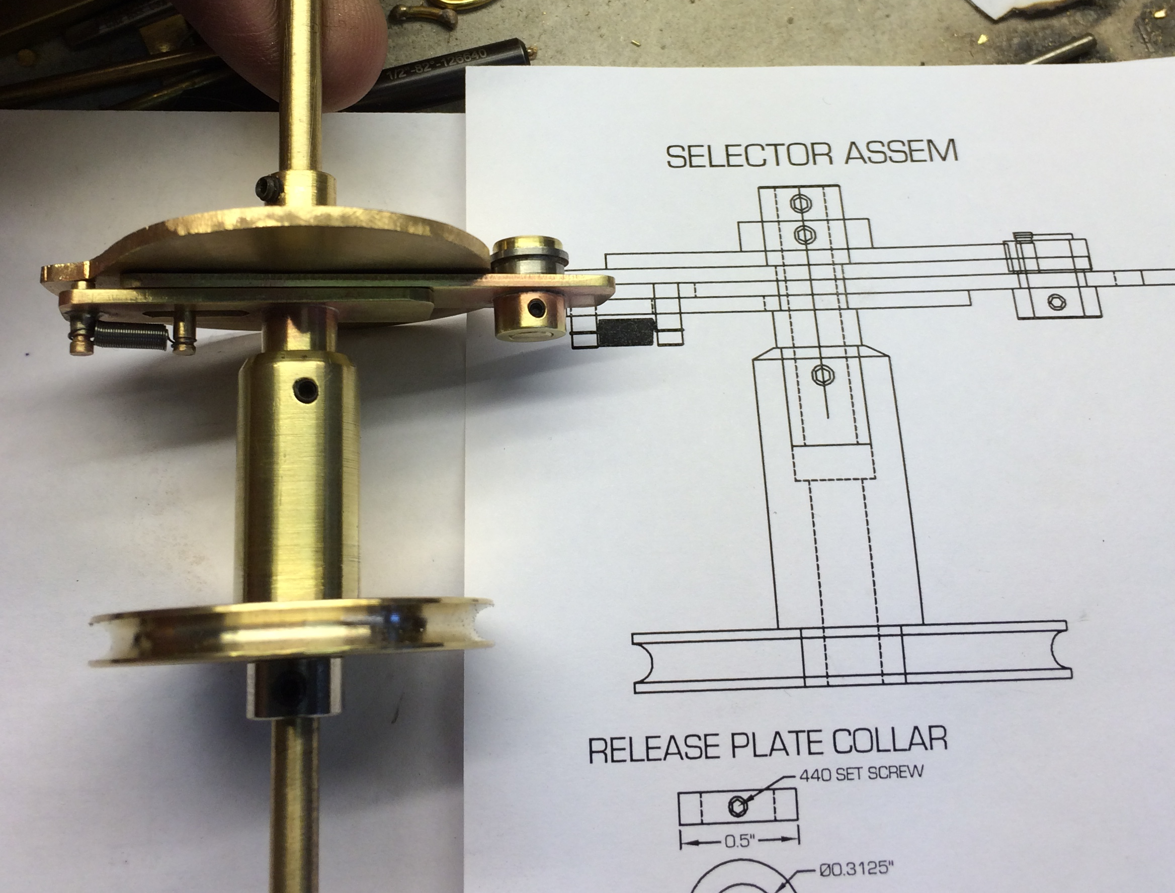
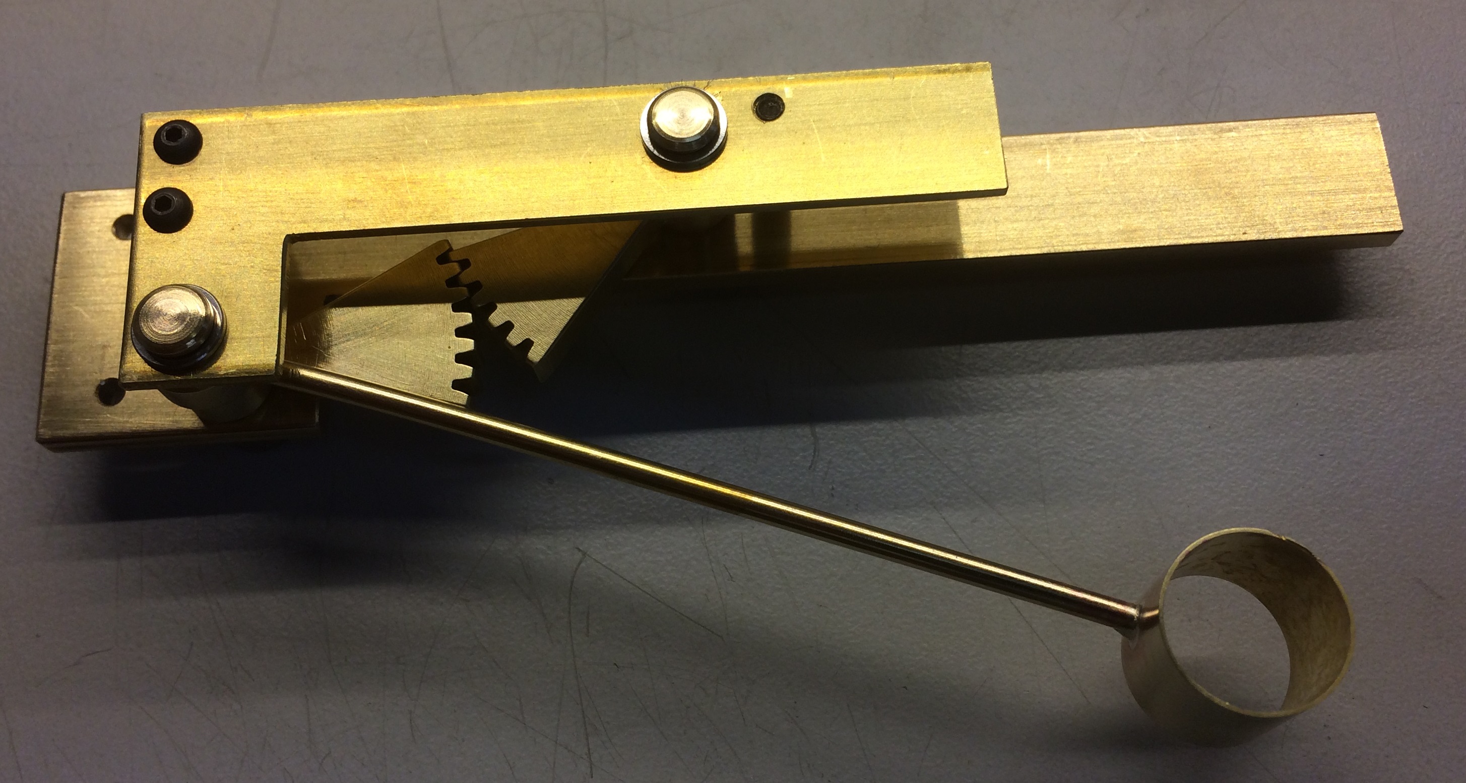
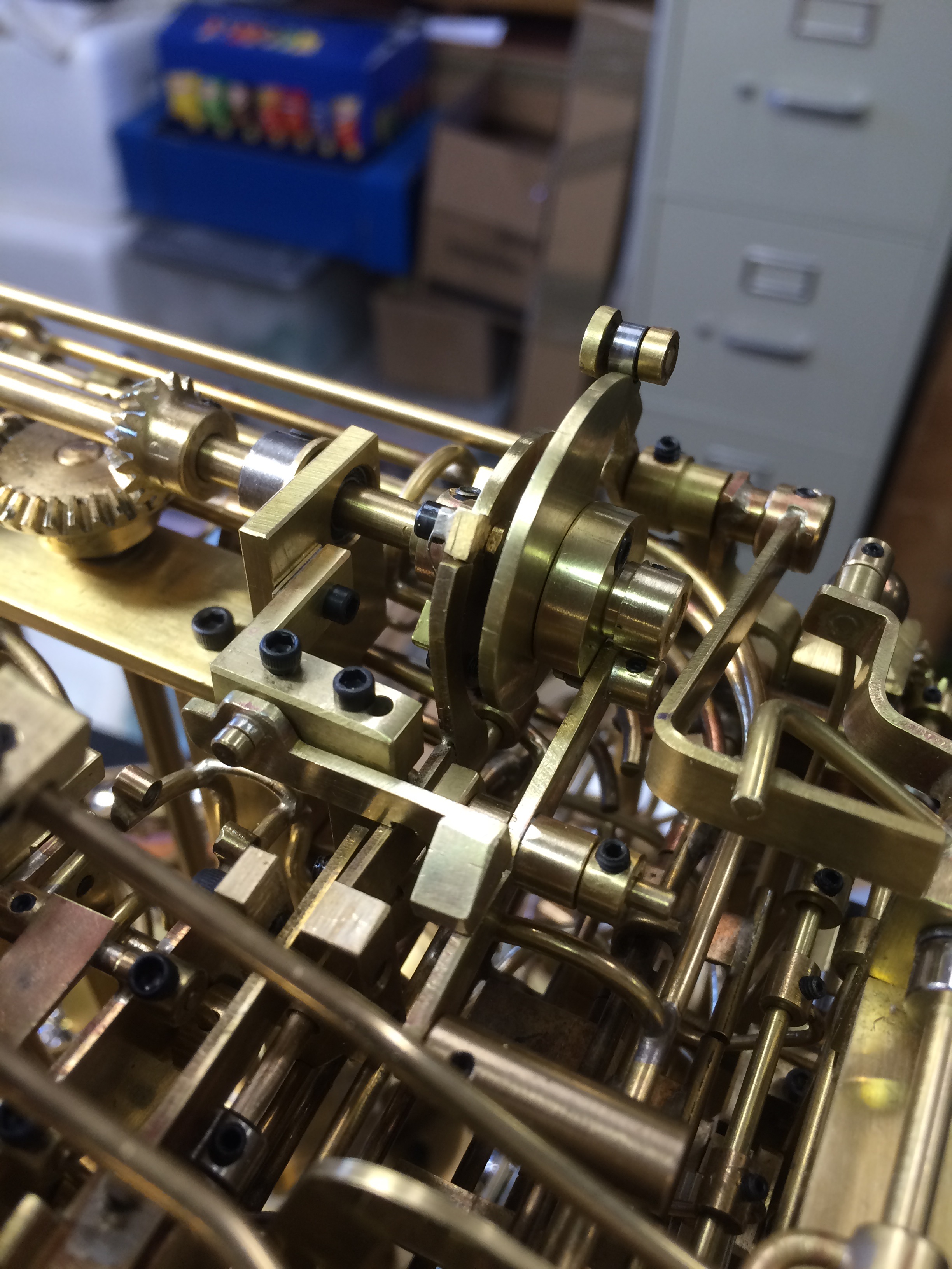
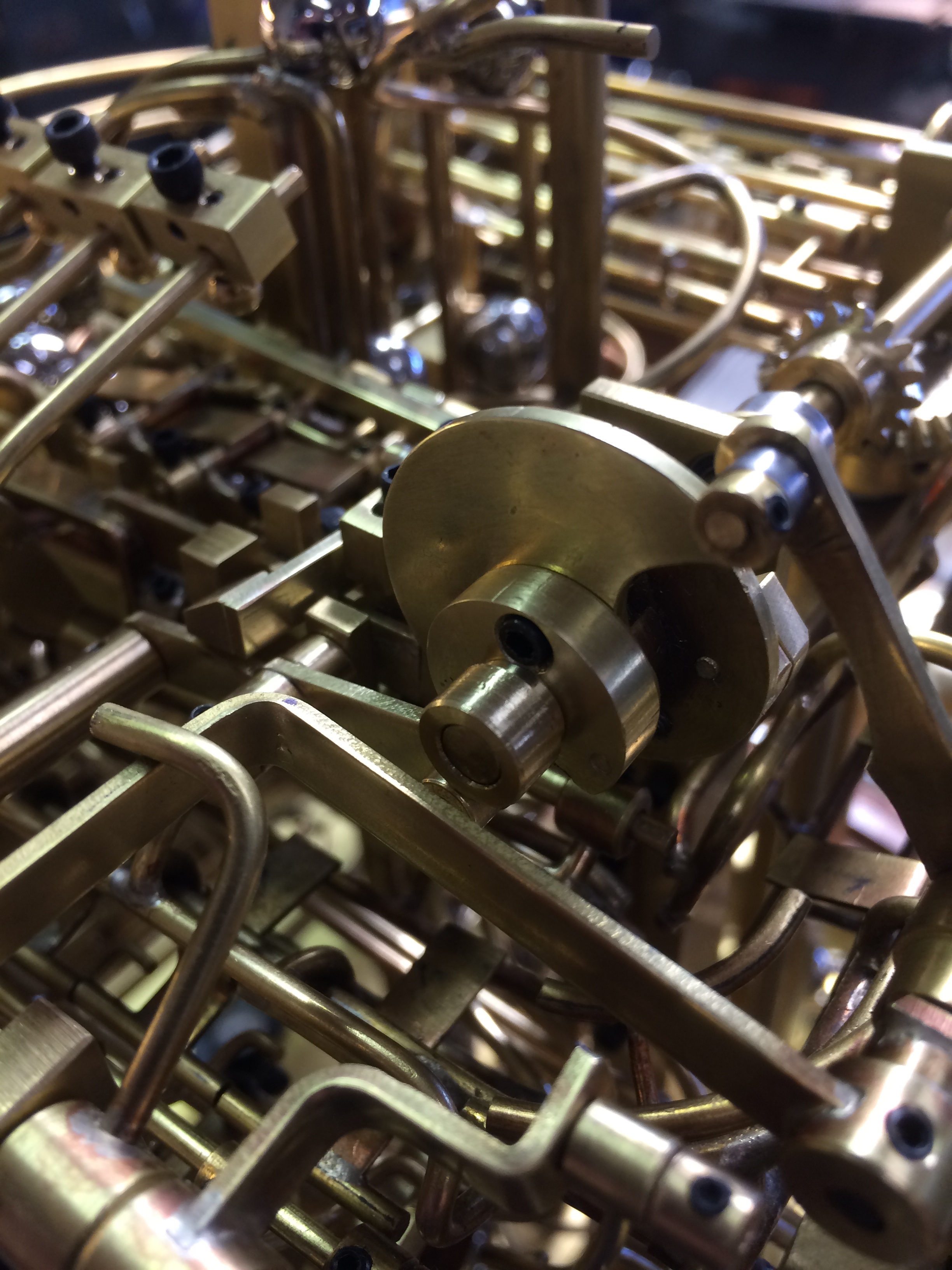
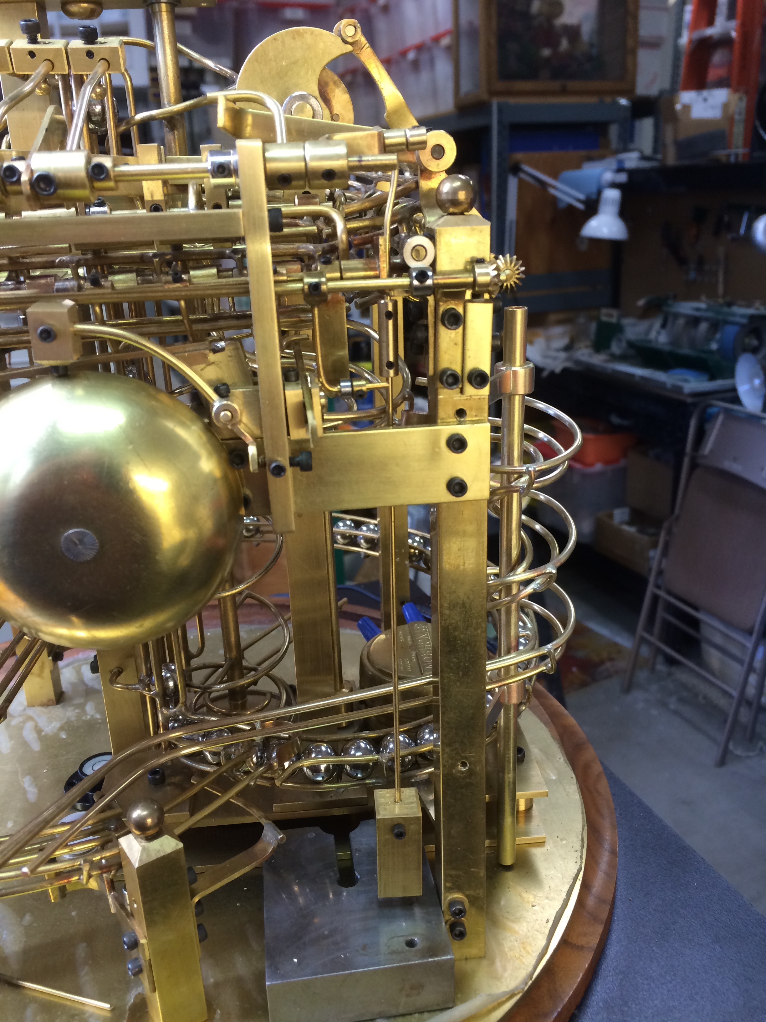
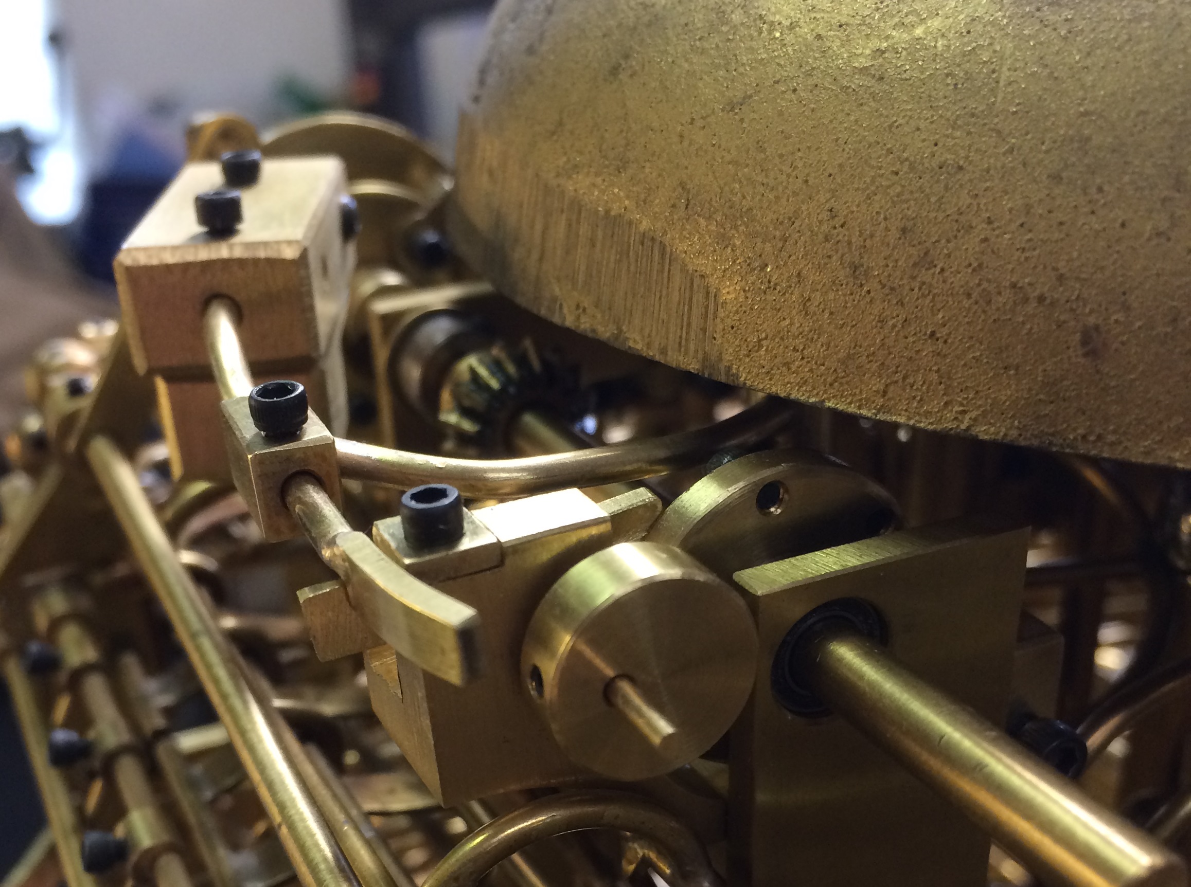
I ended up making a flanged wheel with a collar that had six socket head screws evenly spaced around one side. Then mounted it on the horizontal shaft that turns at 5 rpm.
A block was made that held a small lever with a counter weight and would ride against the screw heads as the shaft turned.
 Since the shaft turns at 5 rpm, that moves the lever 30 times a minute or every two seconds.
A plate was added to the hammer arm that when the hammer cocked, it could be latched by the lever until released as the shaft turned.
The balls were originally moving into the hour lever about every second or so. Now when the first one arrives and operates the hammer, the second ball will cock and latch the hammer until released. This creates a strike every two seconds. (See Movie)
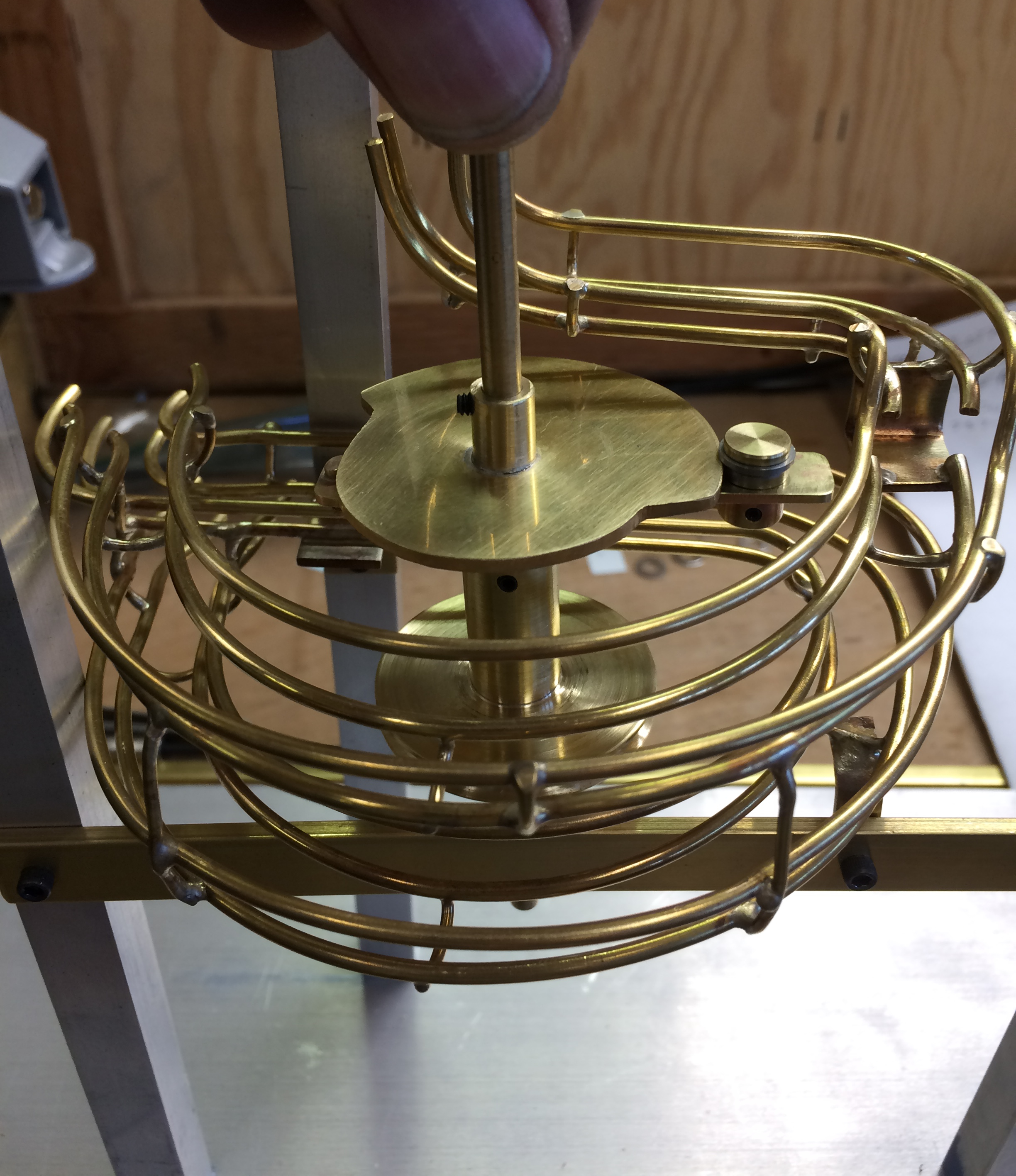
Now it is time to work on the selector for releasing the proper number of balls for the hour. I’m pretty sure this will be the biggest challenge yet.
Note: In the last three months I have spent untold hours trying to get the main bell to be louder and finally replaced it with a larger one that works much better. There were a couple of gremlins that popped up and demanded attention as well which required some rework of the track. I also replaced some work I had done earlier that I wasn’t happy with. It is pretty normal to see a better way after you have done something. This post covers a fair amount of time and progress not really noticeable.
It has been very hot here in Arizona the last month and that has made it difficult to work in the garage. And then there were the four days I spent in the hospital and recoup after that didn’t help too much.
Anyway, things are back on track and we will see how things go from here.

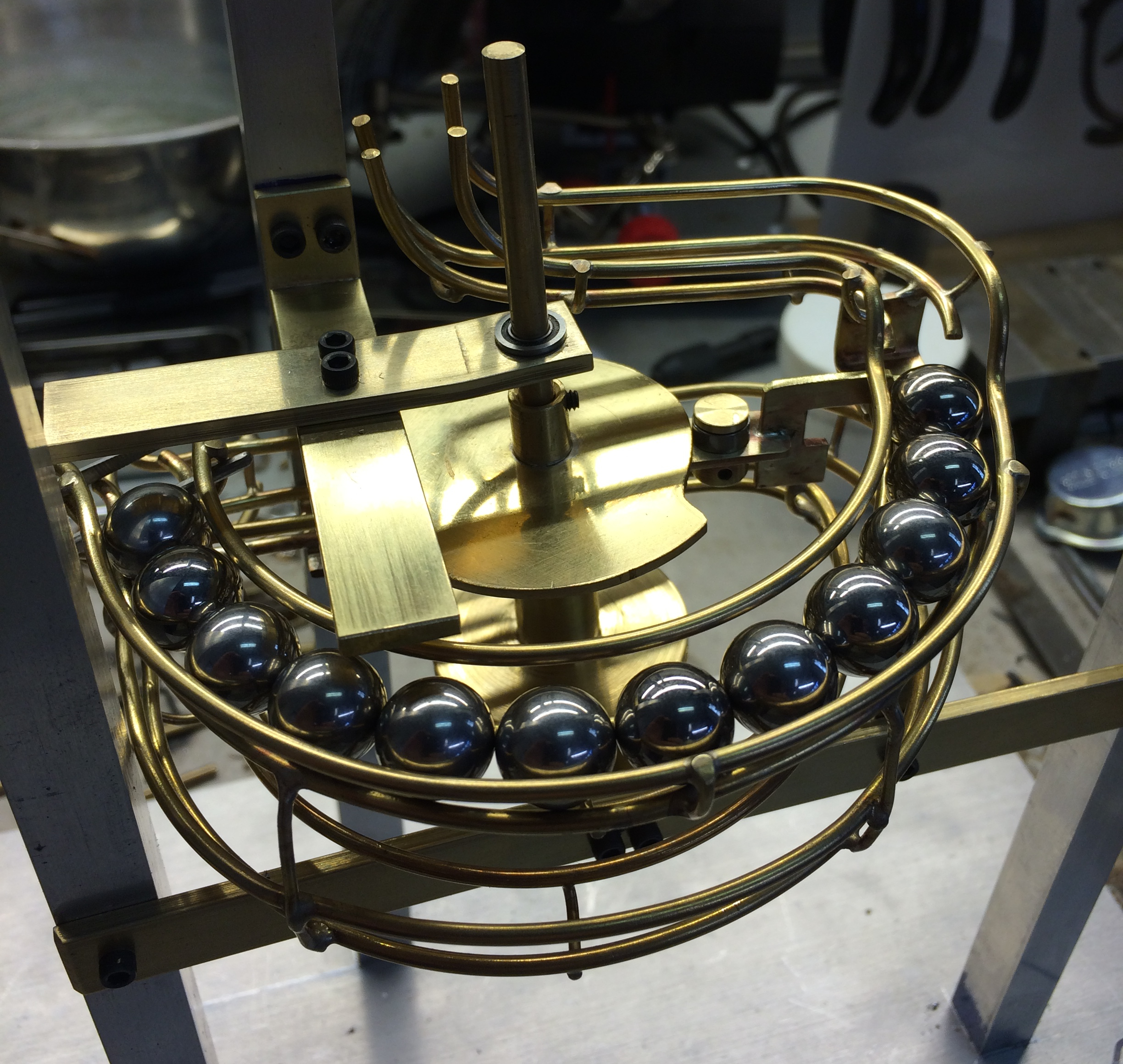 Once it contacts the balls in the upper rack, the selector plate will cam out enough to place the lower extension into the balls on the lower rack.
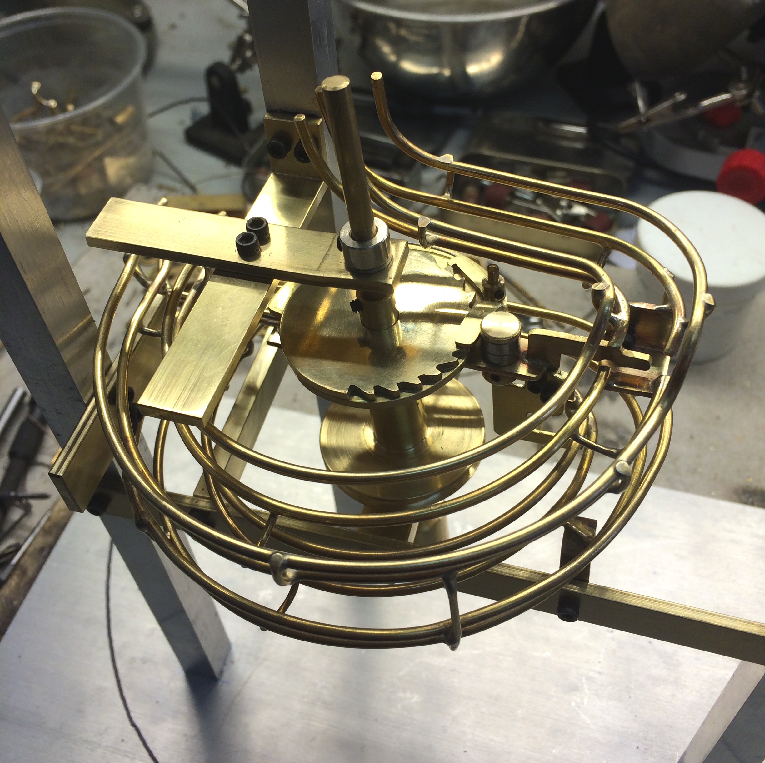 When the selector cams out it allows a pawl to engage with the teeth on the release plate and be carried around by the cam. That action will only happen when the selector has moved.