
 So now I have balls going through the quarter magazine and ending up in the striker mechanism and then no where to go after that.
The excess balls that are not needed for the magazine replenishment also have no where to go.
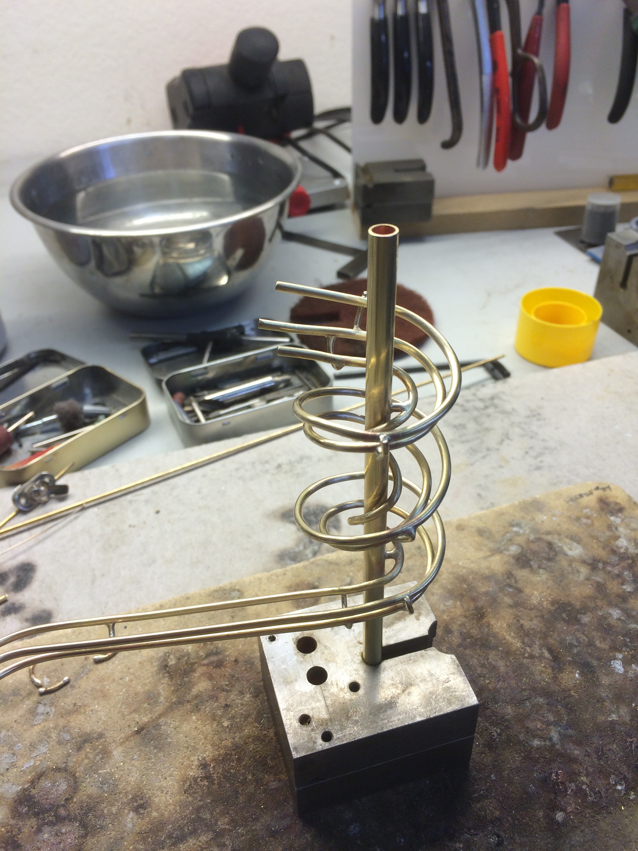
It is time to make more track.
I liked the aesthetic of the spiral for the timing balls and decided to use the same effect on the opposite corner.
I learned a lot about making a spiral from the hiccup with the first one.
So this time it went much easier.
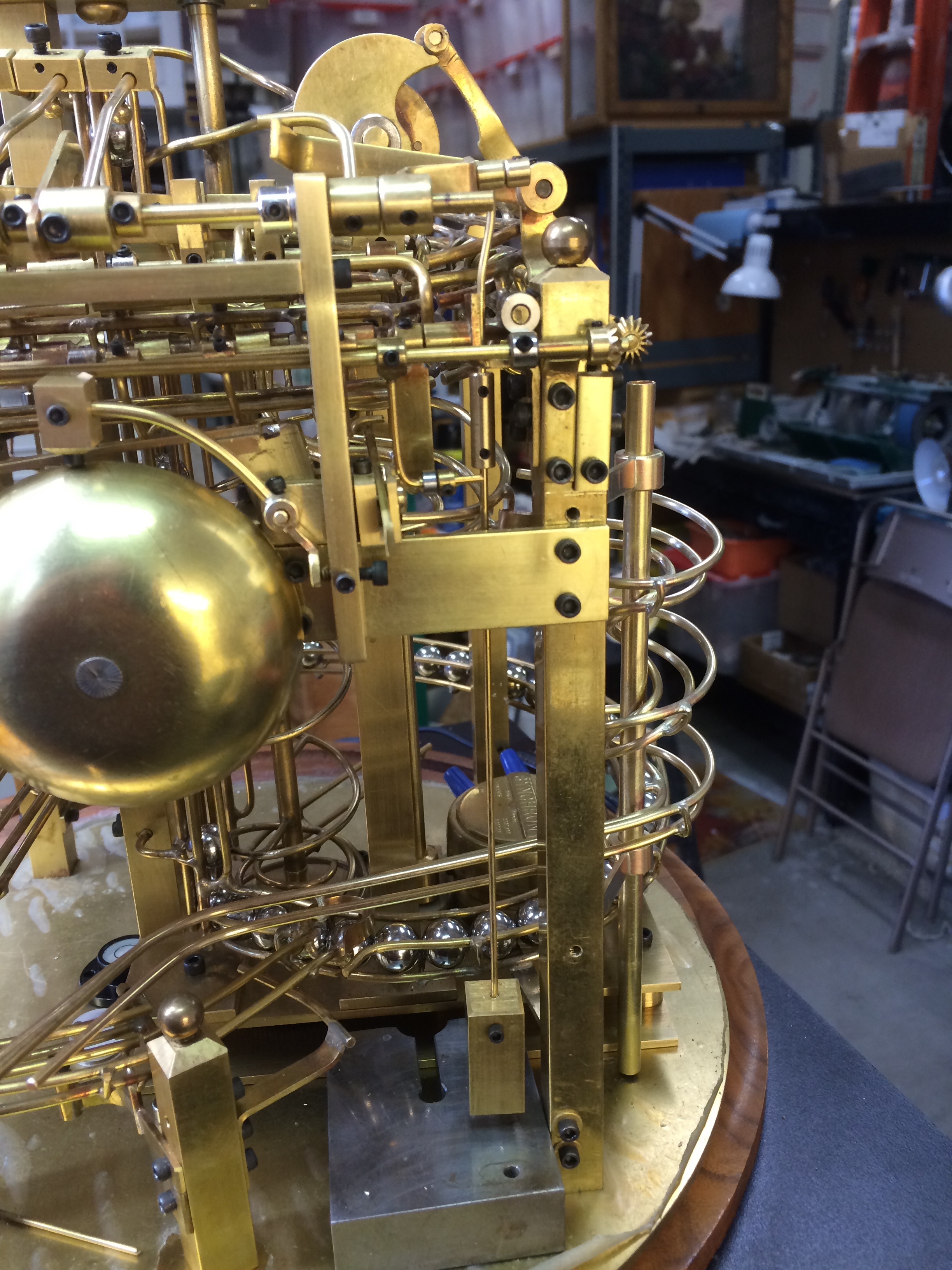
I had to deal with the balls from the excess drop of balls not needed to replenish the quarter magazine and from the quarter hammer lever after the strike and route them back down to the second lift.
A new section of track was made to loop the balls around and over the feed for the first lift.
I noticed pretty quickly that while the striker for the quarter hour worked well, it was almost too well. The strikes were coming faster than I wanted and there was also some inconsistency.
It was obvious that I had more work to do.
The movie shows the hammer action and the balls exiting below to return to the second lift.
Hi Mr. Long,
I have seen the youtube video of your early rolling ball clock. It is indeed a beautiful and interesting thing. Would you answer questions that I have concerning details of its construction which are not easy to make out? Could the clock be made with brass rod or is the phosphorous bronze that you mentioned necessary? Some available phosphor bronzes contain silver and one is composed of just phosphorous and copper. Which did you use? Are the rod diameters 1/16, 3/32 and 1/8 inch? Thank you.
Regards,
Bill Morrison
Wolcott, Vermont
Bill, The brass rod that I use is brazing rod that I get from a welders supply. Sometimes if I need accuracy in the diameter then I will buy rod from hobby shops. The common sizes are 1/16, 3/32, & 1/8 inch. It is easy to find tubing to fit these sizes for pivot points. I also will use 1/4 inch for weights. I have found the 44% or 45% silver solder works the best as it is closer in color to the brass. Originally I was using 56%, but changed about 4 months ago. My torch is a Smith Little Torch. I have found that Micro Mark is a great place for specialty tools. I will be posting more progress on the Clock II, as I play catch up. My son Michael convinced me that I should document the progress so I’m trying to present it in stages as I get the time. Hope this helps. Jon
Jon, Thank you for the response. I began to get confused by alloys in rods for clock parts and alloys in solders and brazing rods. I have purchased rods of the dimension you list that are called brass (just Cu and Sn I think). I will look into the Little Smith torch. It seems to be very versatile for small scale work. I have been getting the Micro Mark catalog. I have fond memories of having played soccer against the Berkeley Heights, N.J. (where Micro Mark is located) team when in the eighth grade. I have never been in a competitive sport since. In your clock of 30 years ago what are the round things at the ends of each of the pivots, nuts or washers? Are the rods in the spindle tubes just butted and soldered as a T to the frame? Or are they in holes with threading? These are some the details which I cannot make out. The frame appears to made of 1/8″ rods, or is it 1/4″?
Regards,
Bill