
 In my last post I talked about the base plate for the clock.
Having the base established, I was able to mount the motor and lift assemble in place. From this I can create a structure to support the rest of the mechanism for the clock.
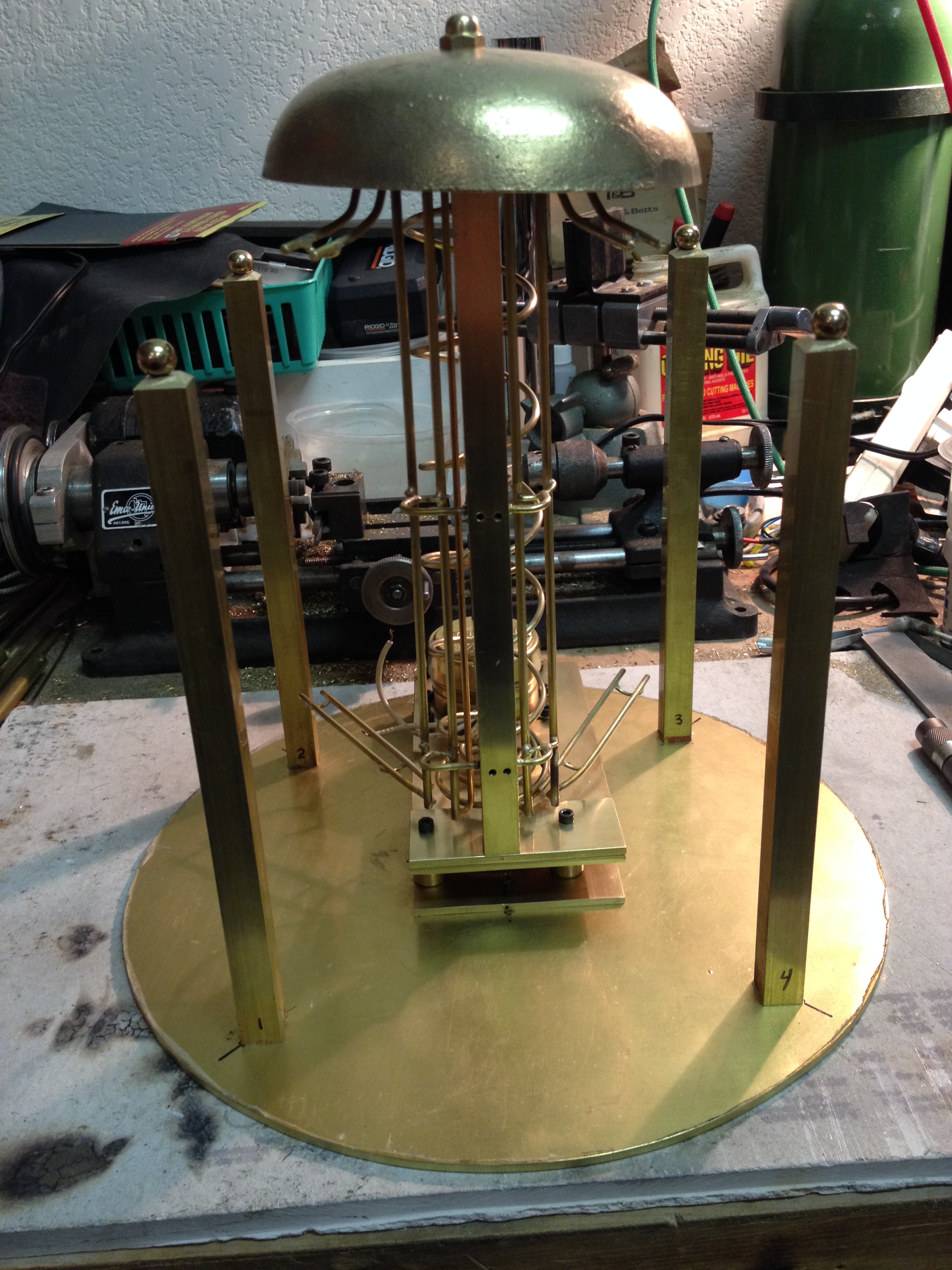
I’m making this up as I go, so I have to remain flexible. I know I will need something solid and with the capability to mount other things to it as we go along. I liked the 1/2″ square rod that I used for the lift and so keeping with that theme, four vertical bars evenly spaced were mounted around the base. They were set back from the edge of the base 5/8″ to allow balls to pass around the outside of the frame.
While the intent wasn’t to get too fancy I did chamfer the top end and put a brass ball on top of each bar to finish them off. I found the balls on-line from Alibaba.com
 The vertical bars are held in place by two 440 flat head socket screws each, tapped into the bottom through the base plate. The bottom cuts had to be square to keep them perfectly vertical. Without a mill, the ends had to be hand filed.
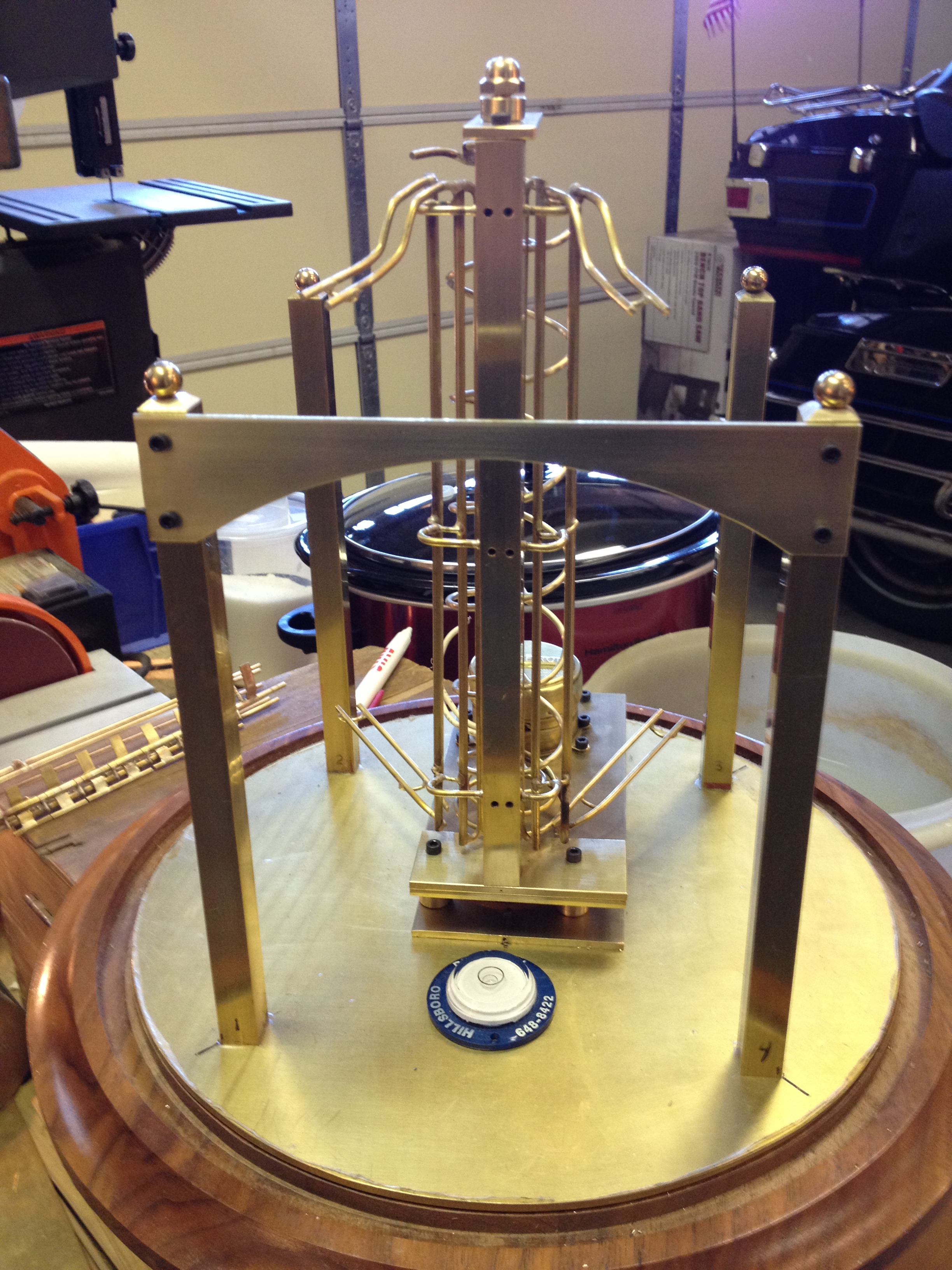
To add a little interest to the design I used a piece left over from cutting out the base as a front brace. I thought the arch it created gave more of a finished look.
I keep a 360 degree level on the base so I know things are all relative to it.
This last photo is a good view of the double lift for the balls.
Next, how to keep track of the number of balls for the 15, 30 &45 minute strike.
Fun times ahead…