
 After completing the reset shafts for the track flips, it became obvious that I needed extra power to drive the reset shafts.
When making the main drive train I left an extra shaft available on the top of the gear box. This shaft turns at 2.5 rpm as the drive train ends up turning the main lift spiral 1 rpm. Remember the lift spiral releases one ball every minute.
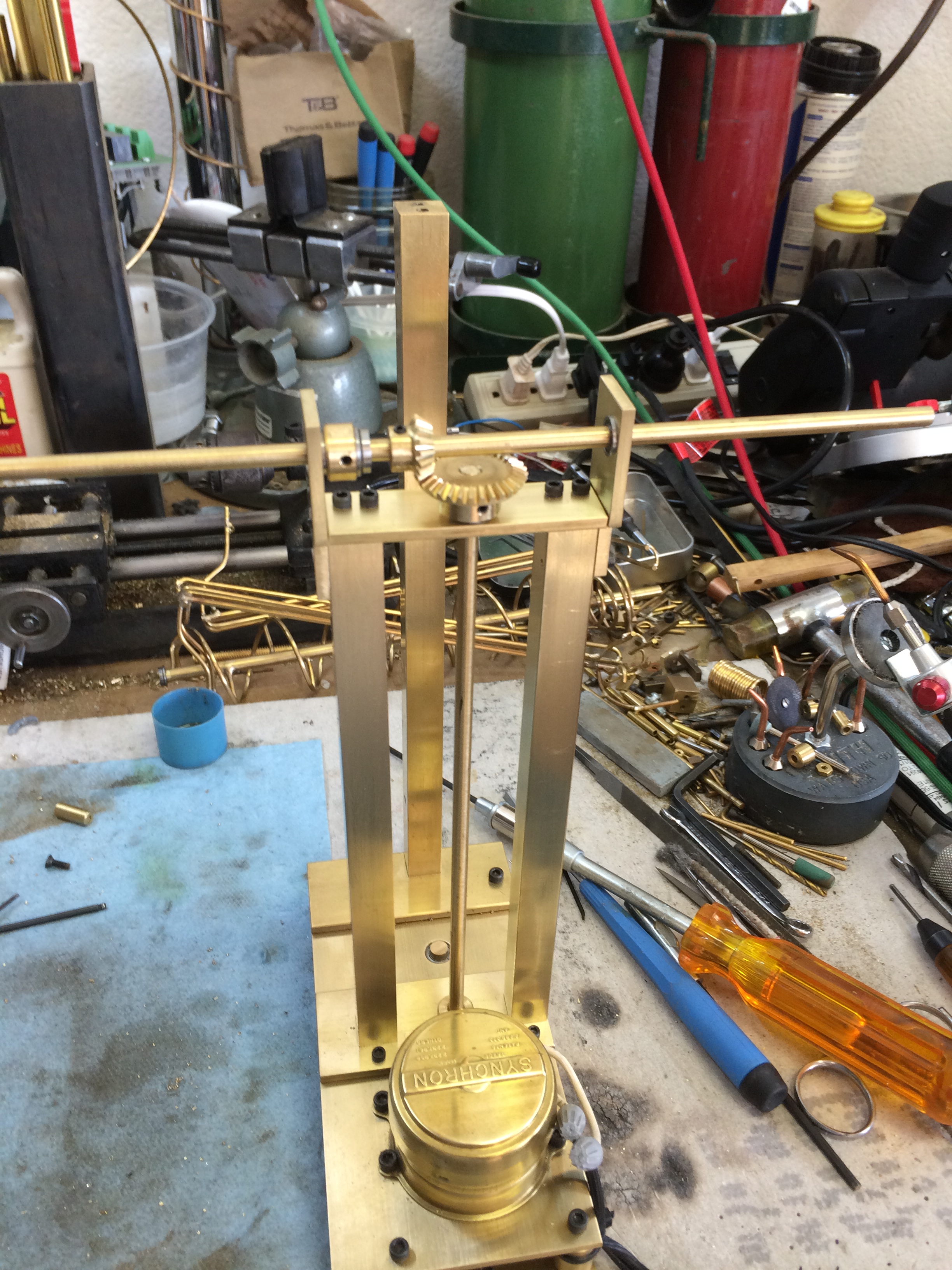
The idea is to make an assemble that is serviceable and removable from the main gear assembly, so that it can be easily modified as the project progresses without disturbing the main drive.
I decided to use the same 1/2″ square bars as I did with the main columns for support and aesthetics. A lower plate was attached for mounting the columns and an upper plate for a housing a bearing and bracing for the horizontal shaft. The drive shaft is 3/16″ diameter brass rod.
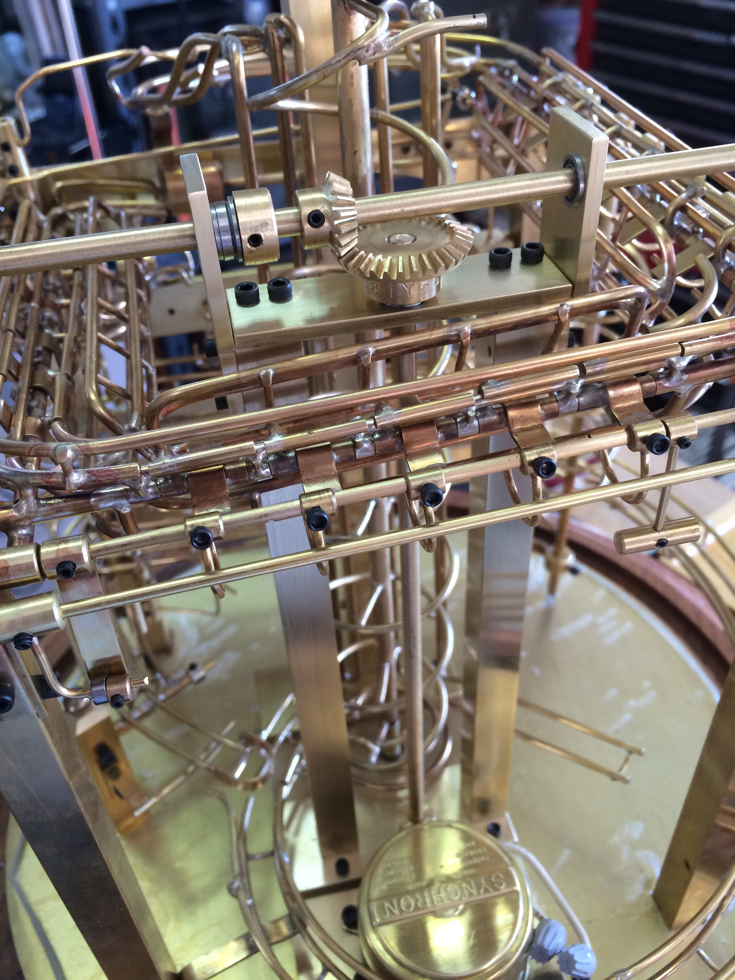 The upper assembly has two (Boston) gears to achieve a 5 rpm of the horizontal shaft. I figured that would give me five opportunities to do something every minute.
Bearings were installed at all points of the assembly.
The trick was to just fit the top of this below the main bell and still have room for power takeoff. I ran the horizontal shaft long in both directions, so if needed it would be there.
The movie shows the beginning of a cam/clutch assembly that will be used to reset the flips. I still have to convert that movement into operating the reset shafts.
Now the next step is to use the power.